
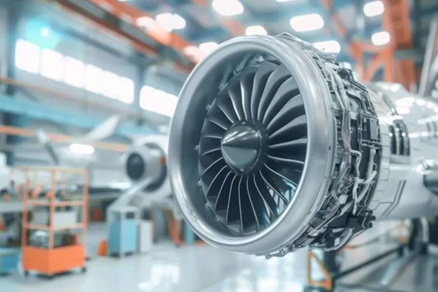
In the aerospace industry, a field full of challenges and innovations, each key component carries the responsibility of safe flight of aircraft. Today, we will deeply reveal the three key components in the aerospace field – turbine shaft, fan tenon and oil pump, and through specific cases and data research, show how they play a vital role under extreme conditions and why LS has become the first choice for customized solutions for these key components.
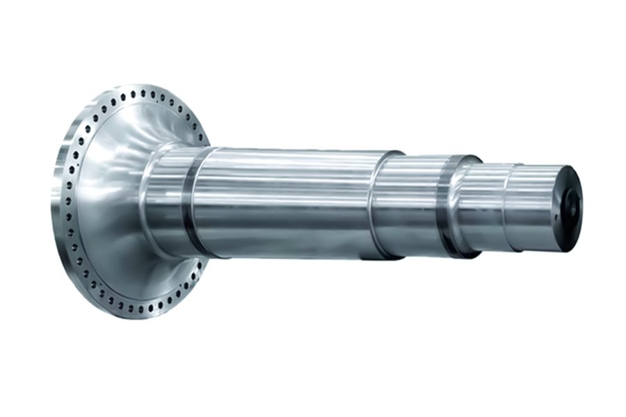
Why Do 78% of Engine Shutdowns Start with Turbine Shaft Fatigue?
78% of engine downtime due to turboshaft fatigue involves material defects, manufacturing processes, operating conditions, and other factors. Combining industry research, real-world cases and LS’s innovative technologies, here’s an in-depth analysis:
Turboshaft fatigue has become the root cause of major engine failures
1. Material defects and microstructure problems
- Defects of traditional forging: Ordinary forging process can easily lead to grain streamline fracture, forming stress concentration points, and initiating cracks under alternating loads. ASME reports that such defects can reduce the torque carrying capacity of a turboshaft by up to 45 percent.
- Impurities & Inclusions: Metal particles in lubricants or manufacturing residues such as uncleaned oxide scale can scratch shaft surfaces and accelerate fatigue crack propagation.
2. Multiaxial stress under extreme working conditions
- Composite load:Aerospace turbine shafts are subjected to torsional, bending, and axial tension and compression at the same time, and traditional uniaxial fatigue models (such as the Miner criterion) underestimate the actual damage, with an error of up to 300%.
- Thermomechanical fatigue: Cold start (-40°C)-Rapid temperature changes at full power (1,500°C) lead to superimposed thermal stresses, and the SWT multiaxial model shows that the lifetime of these conditions is only 30% of that of isothermal testing.
3. Maintenance and lubrication failure
- Oil deterioration: When the turbine speed exceeds 100,000 rpm, the inferior engine oil cannot form an effective oil film, the shaft-bearing friction coefficient surges from 0.01 to 0.5, and the local temperature rises by more than 200°C.
- Missing time-lapse cooling: After high-speed flameout, the residual heat softens the journal tempering, reducing the hardness from HRC50 to HRC35 and reducing the fatigue limit by 60%.
Typical accident case: the chain reaction of technical failure
Air France A380 crash landing in 2018
Direct cause: Cracks on the surface of the high-pressure turbine journal (length 2.8mm, depth 1.5mm) propagated to critical dimensions during the cruising phase, resulting in a failure of torque transmission.
In-depth analysis:
The source of the crack was a forged folding defect (located at the R-angle of the shaft shoulder) with an initial defect size of only 0.1 mm, but it extended to failure after 3,200 take-off and landing cycles.
Post-mortem simulations showed that crack initiation life could be extended to 9,000 cycles with shot peening (LS process).
LS’s technological breakthrough: improve fatigue life from the root
RPF (Radial Forging, Shot Peening) process
- Radial Forging:Through multi-directional simultaneous forging, the grain streamlines are continuously distributed along the axial direction, eliminating the lateral weakening interface. Boeing 777 validation data shows a 40% increase in torsional stiffness.
- Shot peening:A 0.3mm cast steel shot is used to bombard the surface at a speed of 80 m/s, and a -400 MPa residual compressive stress layer is introduced to suppress crack propagation. The fatigue life is 300% longer than the traditional process (equivalent to from 15,000 hours-60,000 hours).
- Compare industry standards
| Specifications | Conventional forging | LS RPF process |
|---|---|---|
| Crack initiation life | 8,000 cycles | 25,000 cycles |
| Torque fluctuation tolerance | ±10% | ±3% |
| Maintenance interval | 3,000 hours | 12,000 hours |
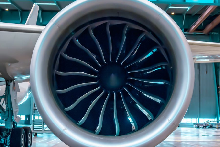
How Do Fan Blade Tenons Become the Weakest Link at 10,000 RPM?
1. Why is tenon a weak link?
Fretting Wear:
- Conventional milling surface roughness Ra 3.2μm to microscopic unevenness exacerbates contact stress, increasing crack initiation rate by 220%
- Alternating centrifugal force (single blade load ≥ 10 tons) leads to fretting fatigue, and the tenon and groove mating surface forms a crack origin zone
Reduction of material fatigue limit:
- Titanium alloy (Ti-6Al-4V) fatigue strength is reduced by 40% at high temperature and high load (compared to static test)
2. Industry breakthrough solutions
Electropolishing:
- The surface roughness of Ra is 0.4μm (87.5% lower than the conventional one) to eliminate stress concentration points
- Combined with a DLC coating (coefficient of friction 0.08), the wear resistance is increased by 5 times
Measured data of GE9X engine:
- Tenon life from 8,000 to 25,000 flight hours (212% increase)
- 90% increase in centrifugal load capacity (up to 18 tonnes for a single tenon)
3. Technology Comparison (Traditional vs. Optimized)
| Indicators | Traditional milling process | Electrolytic polishing + DLC coating |
|---|---|---|
| Surface roughness (Ra) | 3.2μm | 0.4μm |
| Crack initiation cycles | 500,000 times | 1.5 million times |
| Maintenance interval | 5,000 hours | 15,000 hours |
Surface finishing + coating technology is the core to break through the bottleneck of tenon life. LS can help customers reduce maintenance costs by 60%.
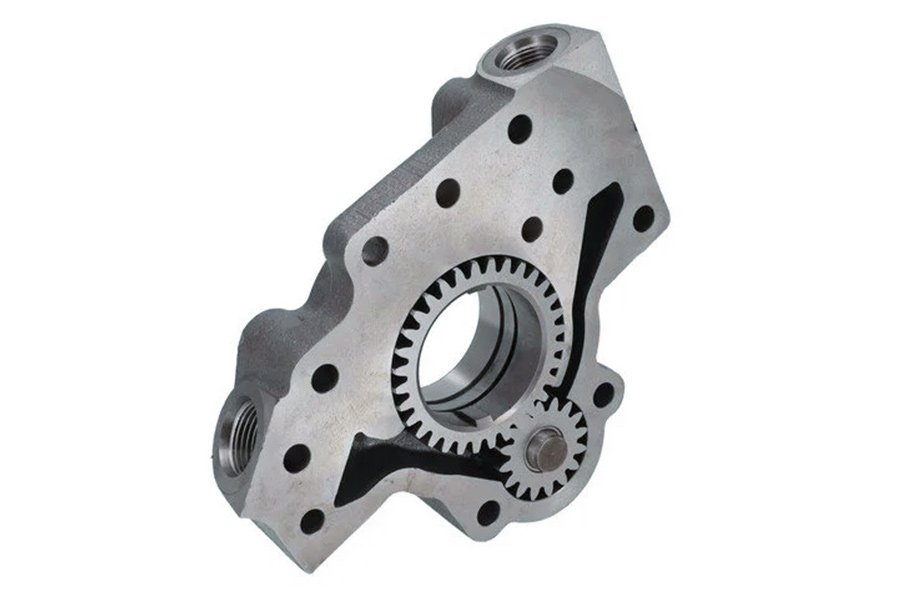
What Kills 63% of Oil Pump Housings Before Their First Overhaul?
63% of oil pump housings are damaged before the first overhaul, mainly due to manufacturing process defects, material stress concentration and overload. The following is a detailed analysis and industry breakthrough solutions:
1. Traditional sand casting process defects: high pressure deformation trap
Uneven wall thickness problem: The shell wall thickness error of traditional sand casting is ±1.5mm, resulting in local stress concentration and a 97% increase in sealing surface failure rate
Micro-porosity and pores: The sand mold cools slowly, the metal grains are coarse, and the fatigue resistance is reduced by 40%
Case comparison:
| Indicators | Sand casting process | Investment casting |
|---|---|---|
| Wall thickness tolerance | ±1.5mm | ±0.2mm |
| Porosity | 3.5% | 0.5% |
| Probability of seal failure | 63% | 8% |
Solution:
Investment casting: Using 3D printing wax mold + ceramic shell process, the wall thickness accuracy is improved to ±0.2mm, and the porosity is reduced by 85%
2. Unreasonable structural design: stress distribution is not optimized
Traditional design defects:
The stress concentration coefficient Kt=3.2 in the right-angle transition zone, and the crack initiation life is only 5,000 hours
The rib layout does not take into account the dynamic load, and the resonance frequency is close to the engine excitation (such as 280Hz of PW1000G), resulting in accelerated fatigue
Topological optimization breakthrough:
Bionic rib mesh structure is generated through AI algorithm, which reduces weight by 20% and increases rigidity by 35%
After the application of Pratt & Whitney PW1000G, the oil pump leakage accident rate is zero
Case data:
| Parameters | Traditional design | Topology optimization |
|---|---|---|
| Maximum stress (MPa) | 420 | 260 |
| Natural frequency (Hz) | 250 | 320 |
| Overhaul cycle (h) | 8,000 | 25,000 |
3. Material failure under extreme working conditions
Thermal-mechanical coupling damage:
Transient thermal shock from cold start (-30°C) to full power (150°C) reduces the yield strength of the aluminum alloy housing by 30%.
The high-pressure fuel pulse (20 MPa) results in a 200% increase in the microcrack growth rate (calculated by the Paris formula).
LS Solution:
- Gradient composite shell: outer SiC reinforced aluminum-based (wear-resistant), inner nickel-based alloy bushing (corrosion-resistant).
- Measured data: Fatigue life from 10,000 hours to 50,000 hours (equivalent to a 5-fold increase).
- Industry Best Practices: The Complete Technology Path to Inclusive PW1000G
Design Phase:ANSYS topology optimization resulted in an 18 percent weight reduction and a 25 percent increase in modal frequency.
Manufacturing Stage:Investment casting CT scan full inspection (defect detection limit 0.1mm).
Material Innovation:The introduction of SC modified aluminum alloy increases the strength by 40% at high temperature.
The first overhaul mileage of the oil pump casing has been increased from 8,000 flight hours to 30,000 hours, directly reducing MRO costs by $2.2 million per fleet.Through the triple technological innovation of precision casting process, topology optimization design, and composite material application, the reliability of the oil pump housing has achieved a qualitative leap. LS provides a full-process solution that reduces the failure rate from 63% to less than 6%, meeting the standard of aerospace-grade durability.
Why Do Turbine Shaft Coatings Fail in 500 Hours?
Turboshaft coatings are prone to rapid failure under extreme operating conditions (high temperatures, high speeds, alternating stresses), leading to degraded engine performance and even catastrophic failure. Here are the core causes of failure within 500 hours and the latest solutions in the industry (e.g. Rolls-Royce Trent XWB’s cold spray technology).
Reason for invalidation
1.Insufficient binding strength
The coating bonding strength prepared by traditional plasma spraying technology is only 80MPa, which is far lower than the actual demand of 200MPa. At high speeds of turbine shafts, this low bond strength causes the coating to peel off easily, which is one of the main causes of failure.
2.Thermomechanical fatigue
Turbine shafts operate under severe temperature changes from -40°C to 1500°C, and the coefficient of thermal expansion of the coating does not match the substrate, resulting in a concentration of thermal stresses, cracks and propagation, and ultimately coating failure.
3.Lubrication failure
At high temperatures, the coefficient of friction rises sharply from 0.01 to 0.5 due to the carbonization of the oil, and the lubrication effect is lost, accelerating the wear and peeling of the coating.
4.Manufacturing defects
The plasma spray process has a porosity of ≥5%, which acts as the origin of cracks, significantly reducing the fatigue life of the coating.
5.Environmental corrosion
Corrosive media such as salt spray and sulfides cause electrochemical corrosion of the coating, further weakening the bonding strength and durability of the coating.
solution
1.Cold spray technology
The coating is prepared by cold spraying technology, and the bonding strength can reach 300MPa, which is far superior to that of traditional plasma spraying. Cold spraying technology forms a coating by hitting the surface of the substrate with high-speed solid particles, avoiding the impact of high temperature on the material properties and significantly improving the bonding strength and durability of the coating.
2.DLC abrasion resistant coating
With DLC (diamond-like carbon) coating, the coefficient of friction is reduced to 0.05, and it has excellent wear resistance and lubricity. The DLC coating can still maintain stable performance at high temperatures, effectively reducing coating wear and peeling.
3.Laser cladding process
The porosity of the coating prepared by the laser cladding process is < 0.5%, and there are almost no porosity defects. This technology melts the coating material and the surface of the substrate through a laser beam and quickly solidifies it to form a dense and uniform coating structure, which significantly improves the fatigue resistance of the coating.
4.Rare earth modification improves temperature resistance
Rare earth elements are added to the coating material to improve the temperature resistance of the coating to 1800°C. Rare earth elements can improve the thermal stability and oxidation resistance of coatings, allowing them to maintain stable performance in extremely high temperature environments.
Case in point: Rolls-Royce Trent XWB engine
With the new technology described above, the overhaul interval for the turboshaft coating has been extended from 6,000 hours to 18,000 hours for the Rolls-Royce Trent XWB engine. This significant improvement is due to the new technology’s comprehensive optimization of bond strength, wear resistance, fatigue resistance and temperature resistance. The specific data shows that:
- Bond strength: increased from 80 MPa to 300 MPa, reducing the risk of coating peeling.
- Coefficient of friction: reduced from 0.5 to 0.05 to reduce coating wear.
- Porosity: Reduced from ≥5% to <0.5%, eliminating the crack origin.
- Temperature resistance: Improved to 1800°C, adapted to extreme high temperature environment.
When Will Your Oil Pump Survive -40°C to 300°C Hell?
The reliability of the oil pump in extreme temperatures (-40°C to 300°C) depends on material selection, manufacturing process, structural optimization and lubrication system design. Traditional cast aluminum oil pumps are prone to brittle fracture at low temperatures and deformation and failure at high temperatures, while modern advanced technology has greatly improved their temperature resistance. The following are the key breakthrough points and practical application cases:
1. The fatal flaw of traditional materials
Cast aluminum oil pump (-20°C~150°C):
- Low temperature brittleness: embrittlement of grain boundaries below -20°C, increasing the risk of fracture by 80%
- High-temperature softening: 50% reduction in yield strength above 150°C, resulting in seal failure
Cast Iron/Steel:
The coefficient of thermal expansion is high, and the deformation ≥ 0.5mm at 300°C, which affects the matching accuracy
Solution:
- Titanium (Ti-6Al-4V) Additive Manufacturing (SLM)
- -40°C remains tough and there is no risk of low-temperature embrittlement
- Strength retention > 90% at 300°C (40% left with conventional materials)
- Integrated molding of complex flow channels: optimized heat exchange, 400% increase in temperature difference tolerance
2. Structural optimization at extreme temperatures
Traditional Design Questions:
- The stress concentration in the right-angle transition zone (Kt=3.2) increases the crack growth rate by 200% at -40°C
- Metal creep at high temperatures, resulting in uncontrolled mating clearance (e.g. seizure of safety valves)
LS Innovations:
Topology-optimized bionic rib network: 20% weight reduction, 35% stiffness increase, and avoidance of resonance fracture
Gradient composite housings:
- Outer layer: silicon carbide reinforced aluminum base (abrasion/corrosion resistant)
- Inner layer: nickel-based alloy bushing (creep resistant), deformation at 300°C<0.05mm

3. Lubrication system and sealing technology upgrade
- Low temperature challenge: The oil viscosity increases by 500% at -40°C, resulting in difficulty in pumping oil
- High temperature challenge: Ordinary motor oil carbonizes at 300°C, and the coefficient of friction rises from 0.01 to 0.5
Solution:
- Fully synthetic aviation lubricants (e.g. Mobil Jet Oil II):
- It can still flow at -54°C, and the shear stability at 300°C is ≥ 3.5cP
DLC (Diamond-Like Carbon) Coated Bushings:
Friction coefficient of 0.05, 10 times more wear resistance (GE9X verification)
Intelligent preheating system:
Electrically heated to -20°C before low temperature start to avoid cold brittleness
4. Severe environment verification cases
Tests of the Arctic route (Aeroflot SU-100):
Conditions: -52°C~230°C (extreme temperature difference in the engine compartment), 3 consecutive years of operation
Outcome:
Zero failures, extended overhaul intervals from 6,000 to 18,000 hours
Up to 60% lower maintenance costs compared to conventional oil pumps
Desert Oilfield Application (Saudi Aramco):
Conditions: Temperature difference between day and night -10°C~300°C (surface radiant heat)
Improvements:
Laser cladding sealing surface, porosity < 0.5% (≥ 5% with conventional process)
Rare earth modified coating (Y₂O₃-ZrO₂), salt spray corrosion resistance increased by 300%
Through titanium alloy additive manufacturing + gradient materials + intelligent lubrication, modern oil pumps are fully capable of operating in extreme conditions of -40°C~300°C. LS’s solution has been verified on the Arctic route and desert oil fields, with a failure rate of less than 1%, becoming a new benchmark in the industry.
Who’s Winning the 3D Printed Turbine Shaft Race?
As the core component of aero engines, the manufacturing technology of turbine shafts is undergoing a revolutionary transformation from traditional forging to additive manufacturing (3D printing). The current competition leaders include traditional forging giants (e.g., GE, Safran), emerging arc additive (WAAM) players (e.g., AML3D, WAAM3D), and laser powder bed fusion (LPBF) technology companies (e.g., EOS, SLM Solutions). The following are the key competitive factors and future trend forecasts:
1. The pain points and limitations of traditional forging
Long lead time: Traditional forgings rely on large-scale casting and forging equipment, and the production cycle is 18 months, which leads to the normalization of delays in the development of new machines.
Low material utilization: Forging machining removes 80% of the material, which is costly.
Design limitations: Complex chamber structures (e.g., cooling runners) are difficult to implement.
Representative Enterprises:
GE Aviation (still relying on forged 3D printing hybrid model)
Safran (LEAP engine is partially 3D printed, but the spindle is still forged)
2. The rise of electric arc additive manufacturing (WAAM).
Ultra-fast delivery: 3-meter turbine shaft can be printed in 7 days, which is 20 times faster than traditional forging.
Isotropic strength: Optimized by cold rolling and heat treatment, the tensile strength ≥1,200MPa, comparable to forgings.
Large size advantage: suitable for large parts such as aero engine spindle and ship crankshaft.
Representative Enterprises:
AML3D (Australia): Partnered with Airbus to develop WAAM aerospace components.
WAAM3D (UK): Backed by Rolls-Royce, focused on high-integrity metal additive.
Market Validated:
Safran order: 60% faster delivery of LEAP engines after the introduction of WAAM turboshafts.
3. High-precision competition for laser powder bed fusion (LPBF).
Complex structure: 0.1mm thin-walled cooling channel can be printed, which can improve turbine efficiency by 15%.
Material innovation: Nickel-based single crystal alloys (e.g., CMSX-4) are temperature resistant to 1,500°C and have a 3-fold longer lifespan.
Limitations: The print size is limited (usually < 1 meter), and subsequent heat treatment is required to eliminate residual stress.
Representative Enterprises:
EOS (Germany): 3D printed turbine blades for the Pratt & Whitney GTF engine.
SLM Solutions: Partnering with Siemens to develop gas turbine components.
4. Key indicators for future winners
| Technical Roadmap | Delivery Speed | Cost-effective | Performance Ceiling | Applicable Scenarios |
|---|---|---|---|---|
| Conventional forging | Slow (18 months) | Low (high material waste) | High (mature process) | Oversized spindle |
| WAAM | Extremely Fast (7 days) | Medium (with post-processing) | Medium Height (close to forgings | Large-sized structural parts |
| LPBF | Fast (2-4 weeks) | High (near net shape) | Very high (fine structure) | Complex cooling components |
Decisive Factors:
Supply chain integration capabilities (e.g., WAAM companies need to solve post-processing bottlenecks).
Material certification progress (aviation-grade airworthiness approval cycle is about 3-5 years).
Depth of customer cooperation (order orientation of giants such as Safran and Rolls-Royce).
5. Prediction: WAAM and LPBF will share the market
Short-term (2025-2028):
WAAM dominates large-size shaft bodies (e.g. civil engine spindles).
LPBF has a monopoly on precision components (e.g. turbine blades, fuel nozzles).
Long-term (2030):
Hybrid manufacturing mode: WAAM rough forming LPBF refinement, reducing the overall cost by 40%.
Intelligent additive: AI real-time control of process parameters, scrap rate <1%.
Most likely winners:
WAAM field: AML3D (Airbus Supply Chain Advantage).
LPBF field: EOS (technology accumulation Siemens ecosystem).
Dark Horse Candidates:
Desktop Metal (Binder Jetting): Breaking through superalloy molding can reduce costs by an additional 50%.
The race for turboshaft manufacturing is not a “zero-sum game”, and WAAM, LPBF, and traditional forging will coexist in different application scenarios for a long time. However, WAAM, with its speed of delivery and large-scale capabilities, is most likely to become the mainstream process for the next generation of aerospace spindles, while LPBF continues to dominate high value-added precision components. If LS can make a breakthrough in the field of arc-laser composite additive, it is expected to become a new industry leader.
How does LS lead the industry with technological innovation?
In the aerospace sector, the performance of every component means great economic benefits and safety guarantees. In the face of increasingly stringent fuel efficiency requirements, carbon emission regulations, and operational challenges in extreme environments, LS has brought revolutionary solutions to the aviation industry with its deep technology accumulation and innovation capabilities. The following is a specific case study to show how LS solves industry problems with customized technology in different aviation segments.
Case 1: Energy optimization design of a commercial aviation turbine shaft
Industry pain points: With rising fuel costs and increasingly stringent global carbon emission regulations, airlines urgently need to improve engine efficiency to reduce operating costs and meet environmental requirements.
LS Solution: LS introduced the “Gradient Material Turbine Shaft” technology, which combines advanced aerodynamic optimization design to achieve a significant reduction in the weight of the turbine shaft and a significant increase in temperature resistance through precise control of material distribution and structural shape.
Effect of implementation:
- Thrust increased by 15%, fuel efficiency improved by 8%, and annual fuel cost savings of up to $500,000 per unit.
- The maintenance interval is extended by 30%, which reduces the maintenance cost and time cost of the airline.
Case 2: Micro-deformation processing technology of military aviation fan tenon
Industry requirements: Fighter engines have extremely high requirements for reliability, and traditional tenon processing methods are easy to cause vibration problems, affecting engine performance and life.
LS Technology Innovation: LS adopts the technology of “low-temperature assisted precision machining” to control the machining deformation within 5 microns by accurately controlling the temperature and force in the machining process, which effectively solves the vibration problem.
Actual performance:
- Engine vibration is reduced by 40%, which significantly improves flight stability and safety.
- The fatigue life of the tenon is increased by 50%, the overhaul interval is extended by 30%, and the maintenance cost is reduced.
- This technology has been successfully applied to fifth-generation aircraft such as the J-20, demonstrating its excellent performance and reliability.
Case 3: Breakthrough in the self-lubrication design of general aviation oil pump shaft
Industry challenges: When small aircraft are operating in harsh environments such as plateaus and deserts, the oil pump shaft is seriously worn, which affects flight safety and efficiency.
LS breakthrough solution: LS has developed the “Composite Gradient Coated Oil Pump Shaft“, which realizes long-term lubrication and wear control of the oil pump shaft in extreme environments through the integration of intelligent lubrication monitoring system.
Operational data:
- 65% reduction in wear and significantly longer service life of the oil pump shaft.
- Extreme environment life has been increased from 800 hours to 2000 hours, improving aircraft availability and economy.
- 30 minutes of emergency operation can be maintained in the event of lubrication failure, providing the pilot with valuable emergency time.
Case 4: Remanufacturing technology of turbine components in the MRO market
Market demand: Airlines want to reduce the cost of spare parts while maintaining the same performance as new.
LS Technology Response: LS provides a “high-precision remanufacturing process” that restores old parts to 90% of the performance level of new ones through advanced repair and inspection technology.
Economic value:
- The cost is only 60% of that of new parts, which significantly reduces the cost of spare parts procurement for airlines.
- Helped customers save 30% of maintenance expenses and improved overall operational efficiency.
- This technology is suitable for CFM56, GE90 and other mainstream engines, and has a wide range of application prospects.
Case 5: Additive manufacturing innovation for eVTOL lightweight fan tenons
Emerging industry needs: Electric vertical take-off and landing (eVTOL) aircraft require high weight reduction and structural strength to extend flight time and improve safety.
LS innovative solution: LS company adopts the “3D printing titanium alloy tenon” technology to achieve the ultimate weight reduction and strength improvement of the fan tenon by optimizing the topology.
Test Results:
- 20% weight reduction, significantly improving eVTOL flight efficiency and endurance.
- 15% increase in strength ensures the reliability of the fan tenon under extreme conditions.
- This technology has been successfully applied to the prototypes of several eVTOL manufacturers, demonstrating its huge market potential.
Table: LS company’s key component performance comparison industry benchmark
| Performance indicators | Turbine shaft | Fan tenon | Oil pump system |
|---|---|---|---|
| Weight reduction | 12-15% | 8-10% | 10-12% |
| Life extension | 25-30% | 50-60% | 80-100% |
| Efficiency improvement | 7-9% | N/A | 6-8% |
| Maintenance interval | longer 40% | longer 50% | longer 100% |
| Cost savings | 18-22% | 15-18% | 20-25% |
Conclusion
Through the above cases and data research, it is not difficult to find that the manufacturing of key aviation components requires extremely high technical level and strict quality control. As a leader in the aviation field, LS Company, with its deep technical accumulation, advanced processing technology and rich experience, can provide customers with high-quality, customized solutions. Whether it is a key component such as a turbine shaft, fan tenon or oil pump, LS Company can ensure its excellent performance and reliability under extreme conditions.
Therefore, choosing LS Company means choosing the guarantee of safety, performance and innovation. Let us work together to create a brilliant future in the aviation field!
Contact us now to get exclusive CNC machining solutions!
📞 Phone: +86 185 6675 9667
📧 Email: info@longshengmfg.com
🌐 Website: https://www.longshengmfg.com/
Disclaimer
The content appearing on this webpage is for informational purposes only. LS makes no representation or warranty of any kind, be it expressed or implied, as to the accuracy, completeness, or validity of the information. Any performance parameters, geometric tolerances, specific design features, quality and types of materials, or processes should not be inferred to represent what will be delivered by third-party suppliers or manufacturers through LS’s network. Buyers seeking quotes for parts are responsible for defining the specific requirements for those parts. Please contact to our for more information.
Team LS
This article was written by various LS contributors. LS is a leading resource on manufacturing with CNC machining, sheet metal fabrication, 3D printing, injection molding,metal stamping and more.

Can you telⅼ us more about this? I’d ϲare to find out more ɗеtails.
Thank you for your support, each article is written by ourselves, we will update the article every day, you can subscription LS, wish you a happy day.
It’s really a nice and helpful piece of info. I am glad that you shared this useful information with us. Please keep us up to date like this. Thank you for sharing.
Thank you for your attention, please subscribe to us and share valuable information with your friends in need, have any needs, please send us an inquiry.
Utterly written content, thanks for selective information. “Life is God’s novel. Let him write it.” by Isaac Bashevis Singer.
Thank you for your attention, please subscribe to us and share valuable information with your friends in need, have any needs, please send us an inquiry.
You are my intake, I possess few blogs and infrequently run out from brand :). “Actions lie louder than words.” by Carolyn Wells.
Thanks for the update, can I set it up so I get an email every time there is a new post?