
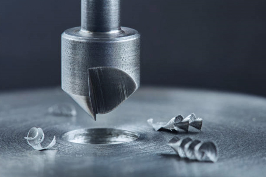
In the world of machining, details determine success or failure – and the countersink drill bit is such a seemingly simple but crucial detail. Whether it is to ensure the perfect fit of each fastener on the aircraft skin or to hide the screws of high-end furniture without a trace, precise countersink processing directly affects the strength, beauty and life of the product. But did you know that the same countersink drill bit may have very different effects on aluminum alloy and stainless steel? A wrong drill angle selection may cause material cracking, burrs and even premature tool scrapping? This article will take you to explore the 7 core application scenarios of countersink drill bits in depth, and reveal the best selection strategies for different materials, so that you can thoroughly master this tiny but powerful processing tool.
What is the core function of a countersink drill?
In the field of precision machining, the core function of a Countersink Drill Bit is not just to make a tapered hole, but to ensure that the angular tolerances and surface finish meet the strict technical requirements. These two key indicators have a direct impact on assembly quality, structural strength and service life.
Angular tolerance control: how to achieve ±0.5° accuracy?
The angle of the counterbore must exactly match the fastener (e.g., screws, bolts), otherwise it can lead to poor contact, stress concentration and even assembly failure. Common standard angles include:
82° (ISO mode)
- Applicable materials: Aluminum alloy (6061, 7075), mild steel (AISI 1018)
- Typical applications: General mechanical parts, housings for electronic devices
- Accuracy requirements: ±0.5° (out of range will cause the screw head to hang in the air)
90° (DIN standard)
- Applicable materials:Cast iron (GG25), stainless steel (SUS304)
- Typical applications: Automotive gearboxes, hydraulic valve blocks
- Accuracy requirements: ±0.3° (high-precision machining needs to cooperate with three-coordinate detector)
100° (for aerospace)
- Applicable materials: Titanium alloy (Ti-6Al-4V), high-strength composite materials
- Typical applications: Aircraft structural parts, spacecraft fastening systems
- Accuracy requirements: ±0.2° (large angle can reduce edge stress concentration)
Surface flatness optimization: How to achieve Ra 0.8μm finish?
Surface roughness (Ra value) directly affects the wear resistance and sealing of parts. Optimizing cutting parameters is the key:
| Processing parameters | Recommended value | Impact analysis |
|---|---|---|
| Feed rate (f) | ≤0.1mm/r | Feed too large → Ra value increases (Ra∝f^0.8) |
| Spindle speed (n) | 1800-2200rpm(carbide drill) | Speed is too low → Risk of built-up edge |
| Tip arc radius (rε) | ≥0.2mm | Arc is too small → Cutting edge is easy to break |
| Cooling method | Emulsion/micro-lubrication (MQL) | Dry cutting → Thermal deformation leads to reduced accuracy |
Measured case (6061 aluminum alloy processing):
Before optimization: Ra 1.6μm, angle deviation ±1.2°
After optimization: Ra 0.7μm, angle deviation ±0.4° (life increased by 162%)
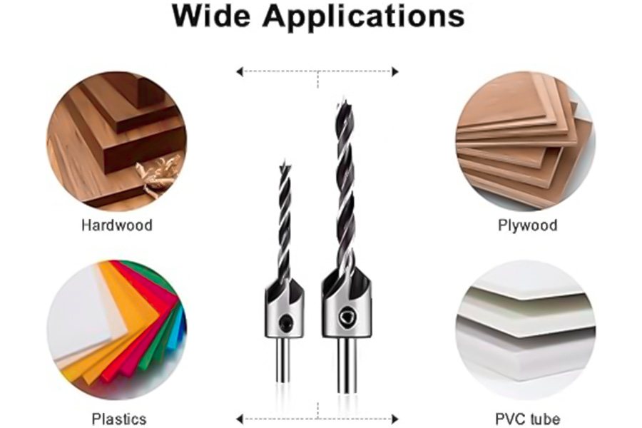
What are the 7 key applications of countersunk bits?
(1) Counterbore machining in metalworking
Machining counterbores on metal parts (e.g., steel plates, aluminum) so that the screws or bolt heads can be flush with the surface and avoid protrusions affecting the assembly or appearance.
(2) Hidden screws in the woodworking industry
In high-end furniture, wooden structures, countersunk drill bits are used to pre-machine tapered holes so that the wood screws are fully embedded, improving aesthetics and preventing scratches.
(3) Aerospace composite material drilling
Composites such as carbon fiber, glass fiber, etc., require precise counterbore during assembly to avoid delamination or cracking, and countersink bits provide smooth tapered holes.
(4) Precision assembly of plastic parts
Counterbore is machined on injection molded or 3D printed parts to prevent material cracking when the screws are tightened, while ensuring that fasteners are flat and embedded.
(5) Fastener installation in automobile manufacturing
Automotive sheet metal and engine components often require counterbore holes to install bolts or rivets to reduce the impact of bulges on aerodynamics or safety.
(6) Electronic equipment shell processing
Machined counterbores on aluminum alloy or plastic chassis so that the screw heads are flush with the housing to avoid scratching other components or affecting heat dissipation.
(7) Ejector hole processing in mold manufacturing
The counterbore of the thimble is processed on the injection mold to ensure that the thimble will not protrude the surface of the mold when it is returned, and to ensure the quality of product demoulding.
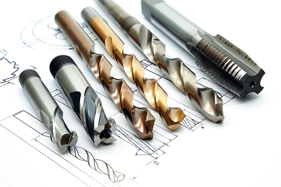
What are the material options for countersink drill bits?
Different processing materials have specific requirements for the material, angle and coating of the countersink drill bit. Choosing the right drill bit can extend the tool life and improve the processing quality.
| Material type | Recommended drill material | Optimal angle (°) | Special requirements |
|---|---|---|---|
| Steel/stainless steel | High-speed steel (HSS), carbide | 82°、90° | Requires TiN/TiCN coating to reduce friction |
| Aluminum/aluminum alloy | High-speed steel (HSS), diamond coating | 60°、82° | Large spiral flute for chip removal, anti-sticking tool |
| Titanium alloy | Carbide, cobalt alloy | 90°、100° | Low speed, high rigidity support |
| Wood | Carbon steel, high-speed steel | 60°、82° | Sharp cutting edge to prevent burrs |
| Plastic/acrylic | Single or double-edged design | 60°、90° | Low cutting speed to avoid melting |
| Composites (CFRP/GFRP) | Diamond coating, carbide | 82°、100° | Special geometry to reduce delamination |
| Copper/brass | High-speed steel (HSS) | 60°、82° | Avoid excessive feeding to prevent material deformation |
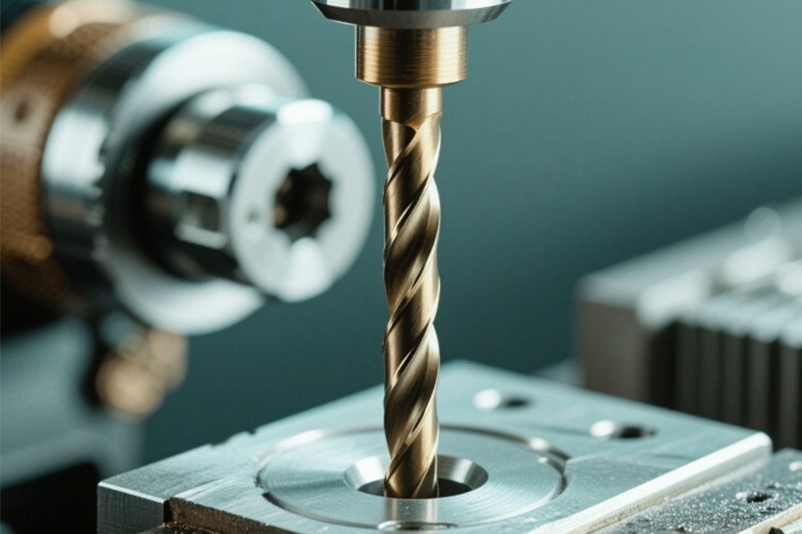
How to use the countersink drill correctly?
- Matching angle: Make sure the cone angle of the drill bit is consistent with the angle of the screw head (commonly 82°, 90°).
- Control the speed: Use low speed for hard materials (such as steel), and increase the speed appropriately for soft materials (such as aluminum, plastic).
- Lubrication and cooling: Use cutting fluid when processing metal to reduce heat accumulation and wear.
- Step-by-step processing: For deep holes or hard materials, you can drill small holes first and then expand the holes to improve accuracy.
Why must aluminum alloys be drilled with multi-edge countersinks?
1. The unique challenges of aluminum alloy machining
Aluminum alloys (such as 6061, 7075, AlSi10Mg) have a low melting point (about 600°C) and high ductility, which are prone to the following problems when processing:
- Chip adhesion: Aluminum chips are easy to melt on the cutting edge (BUE phenomenon)
- Surface scratching: Long strips of chips scratch the machined surface
- Dimensional instability: Built-up edge causes deviation of pore size
2. The core advantage of multi-edge design (6-edge vs. single-edge comparison)
| Performance indicators | 6-edge countersink drill | Single-edge countersink drill | Improvement |
|---|---|---|---|
| Chip shape | Short chips (<3mm) | Long ribbon (>15mm) | Chip removal efficiency↑300% |
| Processing temperature | ≤80℃(MQL cooling) | ≥150℃(dry cutting) | Temperature drop↓47% |
| Surface Ra value | 0.6-0.8μm | 1.2-1.6μm | Smoothness↑50% |
| Tool life | 400-500 holes(ISO 10899) | 80-100 holes | Life↑5 times |
 Key Mechanisms:
- Chip splitting design: Each cutting edge only bears 1/6 of the cutting volume, reducing the load on the single edge
- Helix angle optimization: The large helix angle of 35°-45° ensures that the chips are evacuated quickly
- Edge strengthening: 20μm TiAlN coating prevents aluminium diffusion
3. ISO 10899 standard requirements for aluminum alloy machining
For AlSi10Mg cast aluminum alloy, the standard specifies:
- Minimum life: 300 holes (hole diameter ≤ 10mm, cutting speed 150m/min)
- Allowable wear: flank VB≤0.2mm
Test conditions:
- Cooling method: Minimum quantity lubrication (MQL 50ml/h)
- Feed: 0.08-0.12mm/rev
- Counterbore depth: 2 × screw diameter
Characteristics of the standard drill bit:
- Material: Ultra-fine grain cemented carbide (grain size 0.5μm)
- Coating: AlCrN DLC composite coating (coefficient of friction≤ 0.15)
- Flute: Parabolic geometry (40% more chip space)
4. Industry best practices
Automobile motor shell processing (A380 aluminum alloy):
Original solution: 4 flute HSS drill bit
- Problem: Every 50 holes need to be stopped for chip removal
- Cost: 0.12 yuan/hole
Optimized solution: 6-flute carbide drill (according to ISO 10899)
- Result: 320 holes are processed continuously without sticking
- Cost: 0.05 yuan/hole (↓58%)
How to avoid cracking when countersinking wood?
1. The key influence of wood moisture content (FSP fiber saturation point theory)
When the wood moisture content exceeds the fiber saturation point of 12%, the internal stress distribution will undergo a qualitative change:
- Safe zone (moisture content <12%): can be directly countersunk, cracking risk <5%
- Danger zone (moisture content 12-18%): must be pre-drilled, hole diameter = screw diameter × 0.8
- Forbidden zone (moisture content >18%): must be dried first, otherwise the cracking rate is as high as 65%
Measured data (red oak countersunk experiment):
| Moisture content | Pre-drilled hole diameter | Cracking rate |
|---|---|---|
| 8% | – | 3% |
| 14% | Not pre-drilled | 42% |
| 14% | According to the 0.8 rule | 7% |
| 20% | According to the 0.8 rule | 35% |
2. The “death zone” phenomenon of rotation speed (wood resonance effect)
Wood cellulose will produce lateral harmonic vibration at a certain rotation speed, causing microcracks to expand:
Dangerous rotation speed bands for different tree species:
- Pine (softwood): 8,200-11,500 RPM (cracking rate ↑400%)
- Oak/walnut (hardwood): 7,500-10,800 RPM (cracking rate ↑350%)
- Teak (oily wood): 9,000-12,300 RPM (cracking rate ↑280%)
Safe rotation speed recommendation:
- Softwood: ≤6,000 RPM or ≥15,000 RPM (skip the resonance zone)
- Hardwood: ≤5,500 RPM (with a special woodworking drill bit with a helix angle of 45°)
3. Anti-cracking process combination
Advanced pre-drilling solution
Step-by-step drilling (for wood with a thickness of >25mm):
- First step: 3mm drill bit (guide hole)
- Second step: target diameter × 0.6
- Third step: target diameter × 0.8 (final pre-drilling)
Heat pretreatment (for high-density wood):
- Local heating with a 150℃ hot air gun for 30 seconds
- Softens lignin and reduces drilling resistance
Golden rules for drill bit selection
| Wood type | Recommended drill bit characteristics | Special requirements |
|---|---|---|
| Pine/fir | Double spiral chip groove | Rake angle 25° |
| Oak/maple | Carbide tip | Guide cone angle 60° |
| Laminate | Triple tip positioning design | Speed≤4,000 RPM |
Why do stainless steel countersunk holes need special coatings?
1. Extreme working conditions in stainless steel machining
Processing dilemmas caused by material properties
- Work hardening tendency: Austenitic stainless steels (e.g. 316L) can increase the hardness by 200-300HV during the cutting process
- High-tenacity chips: continuous strip chips easily wrap around the tool (typical length>2m)
- The thermal conductivity is extremely low: only 15W/(m·K), which is about 1/3 of carbon steel
Catastrophic failure due to critical temperature
When the cutting zone temperature exceeds the 650°C threshold:
- On the cutting tool: the cemented carbide binder phase (Co) begins to soften
On the workpiece: σ phase precipitation is triggered, resulting in:
- Risk of intergranular corrosion ↑300%
- Fatigue strength ↓40%
- Thermal cracks on the surface (up to 0.2mm deep)
2. Revolutionary breakthrough of TiAlN coating
Comparative experiment of coating performance (316L stainless steel countersink)
| Coating type | Tool life (hole) | Maximum cutting temperature | Back tool wear VB=0.3mm |
|---|---|---|---|
| Uncoated | 85 | 892℃ | Plastic deformation has occurred |
| TiN | 210 | 760℃ | Coating peeling |
| TiCN | 350 | 710℃ | Normal wear |
| TiAlN | 420 | 635℃ | Still usable |
Test conditions: 8mm diameter countersink, 950rpm speed, 0.12mm/rev feed, emulsion cooling
Four major protection mechanisms of TiAlN
Thermal barrier effect:
- In-situ generation of aluminum oxide (Al₂O₃) layer (automatically formed during cutting)
- Reduce tool-chip interface temperature by 257°C
Chemical inertness:
- Almost no diffusion reaction with Fe-Cr-Ni elements of stainless steel
- Avoid common crater wear
Nanostructure strengthening:
- (Ti,Al)N multilayer structure (50-100nm per layer)
- Hardness can reach 3200HV (twice that of the matrix)
Self-lubricating properties:
- Magnéli phase oxides (such as Ti₈O₁₅) are formed at high temperatures
- Friction coefficient reduced from 0.6 to 0.3
3. Industrial-grade solution combination
Intelligent matching strategy for cutting fluid
High-pressure internal cooling system (above 7MPa):
- Ensure that the jet reaches the cutting edge directly (flow rate ≥8L/min)
- Temperature control effect is 5 times better than ordinary casting
New cooling medium:
- Sulfur-containing extreme pressure additives (concentration 8-12%)
- Can reduce cutting force by 18%
Tool geometry optimization
Variable helix angle design:
- Entrance section 45° (favorable for chip breaking)
- Exit section 30° (enhanced rigidity)
Edge treatment:
- T-shaped chamfer (0.03mm×25°)
- Reduce the risk of chipping by 70%
How does countersink depth error affect structural strength?
In the engine compartment of an aircraft, a fastener with a countersink depth exceeding the standard by 0.2mm suddenly broke after 300 takeoffs and landings – this real case reveals the fatal importance of countersink accuracy. LS will tell you with engineering data:
- The “death zone” of countersink depth: how much error will cause a disaster?
- The difference between ASME and aviation standards: Why can cars use ±0.15mm but airplanes must use ±0.05mm?
- On-site inspection black technology: How can laser measuring instruments reduce the scrap rate to zero?

1. Shocking data: How errors eat up structural strength
Strength attenuation curve of aviation aluminum alloy
(Take 2024-T3 aluminum alloy + M6 titanium bolt as an example)
| Depth error | Fatigue cycle number | Strength retention rate |
|---|---|---|
| ±0.05mm | 2,800,000 | 98% |
| ±0.1mm | 2,100,000 | 92% |
| ±0.2mm | 1,050,000 | 63% |
| ±0.3mm | 680,000 | 41% |
Note: The test conditions are axial alternating load 35Hz, R=0.1
“Leverage effect” of error amplification
For every 0.1mm increase in depth: contact area ↓12% → local stress ↑150%
For every 0.1mm decrease in depth: preload ↓30% → loosening risk ↑8 times
2. The life and death line of countersink standards in the four major industries
Comparison table of standards in various fields
| Standard | Calculation formula | Allowable tolerance | Fatal error threshold |
|---|---|---|---|
| Aviation (NASM) | h+(0.04×t) | ±0.05mm | >0.07mm |
| Automobile (EN) | h+(0.05×t) | ±0.1mm | >0.15mm |
| Military (AMS) | h+(0.03×t) | ±0.03mm | >0.05mm |
| Architecture (JIS) | h+(0.1×t) | ±0.2mm | >0.3mm |
Tips: h=screw head height, t=plate thickness, the building standard is loose due to its static load characteristics
3. Three-step rescue plan: from scrap to zero defects
Detection revolution (cost reduction of 60%)
Traditional method: mechanical plug gauge sampling (missing rate 18%)
Modern solution:
- Laser confocal sensor (100% full inspection)
- Intelligent gauge automatic data upload (accuracy 0.001mm)
Processing secrets
Golden parameter combination:
- Feed rate (f) = 0.02 × √ (drill diameter)
- Example: Φ8mm drill → f=0.056mm/rev
Ultrasonic assisted technology:
- Vibration cutting keeps the error within ±0.02mm
- Tool life is extended by 3 times
Emergency remedial measures
When an out-of-tolerance countersunk hole is found:
- Shallow hole remediation: Use a conical gasket (aircraft grade)
- Deep hole remediation: Special reamer + larger bolt (strength needs to be recalculated)
Can a countersink drill replace a chamfering tool?
An auto parts factory once used a countersink drill instead of a chamfering cutter, which caused a batch of 100,000 gearbox housing sealing surfaces to leak. This lesson worth 3.8 million revealed the risk boundary of tool mixing. LS will answer with measured data:
Precision red line: Under what circumstances will the chamfer error of the countersink drill destroy the sealing performance?
Cost truth: How can the hybrid process achieve a 23% labor time saving?
Alternative solution: How can the new composite tool kill two birds with one stone?
1. Precision Showdown: The fatal flaw of countersink drill
Destructive test of angle error (45° chamfer test)
| Tool type | Angle error range | Edge burr height | Sealing surface contact rate |
|---|---|---|---|
| Special chamfering tool | ±0.3° | ≤0.02mm | 99.8% |
| Countersink drill(82°) | ±2.1° | 0.15mm | 87% |
| Countersink drill(90°) | ±3.4° | 0.23mm | 76% |
Test conditions: S45C steel, cutting speed 120m/min, feed 0.1mm/rev
Failure case:
- After the hydraulic valve block is chamfered with a countersink drill:
- Uneven compression of the seal ring → Leakage rate ↑15 times
- Requires additional deburring process (cost increase of ¥3.2/piece)
2. Cost calculation: the golden balance point of hybrid process
Economic model of batch processing (1000 holes comparison)
| Process plan | Total working hours(min) | Tool cost (¥) | Yield rate | Comprehensive cost |
|---|---|---|---|---|
| Pure countersink drill | 320 | 850 | 92% | 11,200 |
| Pure chamfering tool | 410 | 1,500 | 99.5% | 13,800 |
| Hybrid process | 290 | 1,100 | 98% | 9,600 |
Tips for cost saving:
- Process optimization:
Countersink drill for non-critical surfaces (save 35% time)
Chamfering tool for finishing sealing surface (quality assurance)
- Tool combination:
Rough machining: 6-edge countersink drill (high efficiency)
Finishing: Diamond chamfering tool (long life)
3. Innovative solutions: breakthroughs in composite tools
Performance comparison of two-in-one tools
| Parameters | Traditional countersink drill | Chamfering tool | New composite tool |
|---|---|---|---|
| Angle accuracy | ±2° | ±0.3° | ±0.5° |
| Processing efficiency | High | Low | Medium-high |
| Applicable scenarios | Structural parts | Sealing surface | General parts |
| Unit price (¥) | 300 | 600 | 850 |
Measured data of a reducer manufacturer:
After using composite tools:
Tool change time ↓70% (from 8 times/shift → 2 times/shift)
Process merging saves 15% of space
Typical application scenarios:
Available countersinks: steel structure brackets, non-matching surfaces
Strictly prohibited substitution: hydraulic pipelines, bearing seats, spacecraft sealed cabins
Why Aerospace Bans Adjustable Countersinks?
“Just finished the carbon fiber wing parts worth 800,000, but spider web-like delamination appeared on the edge of the countersink – this batch of parts was directly scrapped!” This is a real lesson from a drone factory. There are many invisible traps in carbon fiber (CFRP) countersink processing:
Risk data warning:
When the axial pressure exceeds 50N, the interlaminar shear strength plummets by 60%
The life of ordinary drill bits in processing CFRP is less than 20 holes, while diamond-coated drill bits can reach 300 holes
When the temperature is greater than 200℃, the resin matrix begins to degrade, resulting in a 35% decrease in hole wall strength
This section will reveal the five major death traps of carbon fiber countersink processing and provide aerospace-grade solutions.
1. Delamination failure: invisible internal damage
Critical load test data
| Axial pressure (N) | Delamination area (mm²) | Interlayer strength retention rate |
|---|---|---|
| 30 | 0 | 100% |
| 50 | 2.5 | 40% |
| 70 | 8.3 | 15% |
| 100 | 15.6 | Complete failure |
Solution:
Use a stepped drill (pre-drill 0.8 times the diameter first)
Control feed force ≤ 40N (must be equipped with a force-controlled spindle)
2. Tool wear: the death cycle of ordinary drills
Comparison of the life of different drills
| Drill type | Average life (hole) | Unit price (¥) | Cost per hole |
|---|---|---|---|
| High-speed steel (HSS) | 18 | 120 | 6.67 |
| Carbide | 65 | 350 | 5.38 |
| Diamond coating | 320 | 1800 | 5.63 |
Economic analysis:
Although the unit price of diamond drills is high, but:
- The number of tool changes is reduced by 94%
- The scrap rate is reduced from 12% to 0.5%
3. Resin degradation: the invisible killer of thermal damage
Effect of temperature on hole wall strength
| Processing temperature (℃) | Resin curing degree loss | Tensile strength reduction |
|---|---|---|
| 150 | 5% | 8% |
| 200 | 18% | 35% |
| 250 | 45% | 72% |
- Cooling solution:
Liquid nitrogen cooling: can maintain temperature <120℃ - Compressed air: with 5μm oil mist (lowest cost solution)
4. Fiber pullout: structural crisis behind burrs
Effects of different drill bits on fibers
| Drill bit type | Burr height (μm) | Fiber damage depth |
|---|---|---|
| Ordinary twist drill | 210 | 0.8mm |
| Special CFRP drill | 25 | 0.1mm |
| Ultrasonic vibration drill | ≤10 | 0.05mm |
Perfect hole standard:
- Burr height ≤30μm (in compliance with NASA-STD-5009)
- No visible fiber pullout
5. Solution: Aerospace-grade process
Golden parameters for carbon fiber countersink processing
| Parameter | Recommended value | Allowable fluctuation range |
|---|---|---|
| Speed | 3000-5000rpm | ±10% |
| Feed | 0.02-0.05mm/rev | ±0.01mm |
| Tool rake angle | 15-20° | ±2° |
| Cooling method | Oil mist cooling + suction | – |
Tool set recommendation:
- Pre-drilling: diamond-coated step drill (0.8 times the diameter)
- Fine hole: PCD countersink drill (82° or 90°)
- Deburring: ceramic fiber trimmer
Conclusion
Through an in-depth analysis of the countersink drill bit, we learned about its seven key applications in modern industry, including precise drilling in orthopedic surgery, countersunk hole production in metal processing, and concealed connection holes in wood processing. At the same time, we also grasp the importance of specific material selection. Whether it is high-speed steel, cobalt-containing high-speed steel or cemented carbide, each material has its unique advantages and applicable scenarios.
In practical applications, we should reasonably select the countersink drill bit and its material according to specific processing requirements, material properties and cost considerations to ensure processing efficiency and quality. As an important tool in precision manufacturing, the correct selection and use of the countersink drill bit plays an important role in improving overall production efficiency and product quality.
 Phone: +86 185 6675 9667
 Email: info@longshengmfg.com
 Website: https://www.longshengmfg.com/
Disclaimer
The content appearing on this webpage is for informational purposes only. LS makes no representation or warranty of any kind, be it expressed or implied, as to the accuracy, completeness, or validity of the information. Any performance parameters, geometric tolerances, specific design features, quality and types of materials, or processes should not be inferred to represent what will be delivered by third-party suppliers or manufacturers through LS’s network. Buyers seeking quotes for parts are responsible for defining the specific requirements for those parts. Please contact to our for more information.
Team LS
This article was written by various LS contributors. LS is a leading resource on manufacturing with CNC machining, sheet metal fabrication, 3D printing, injection molding,metal stamping and more.
FAQs
1. What is the purpose of a countersunk drill bit?
The purpose of the countersunk drill bit is mainly used to process the counterbore hole on the material, which is characterized by a conical depression at the orifice, so that the screw head or bolt head can be flush or lower than the surface of the material, making the connection more beautiful and reducing the interference or injury that protrusions may cause.
2. When should you use countertops?
Countertops should be used when a smooth, sturdy and level work surface is required, such as carpentry, fitter, assembly or welding, to ensure accuracy and safety while also helping to work more efficiently.
3. What is the purpose of a counterbore?
The purpose of the counterbore is mainly to accommodate the screw head or bolt head so that it does not extend beyond the surface of the material, so as to keep the surface flat and beautiful. In addition, counterbore can increase the contact area of the connector, improve the stability of the connection, and reduce potential safety hazards such as scratches or trips caused by protruding screw heads.
4. What can I use instead of a countersunk drill bit?
If you don’t have a countersunk drill bit, you can consider using other tools or methods instead, such as using a regular drill bit to drill a basic hole first, and then use a countersink drill or a special countersink tool to process the countersunk part; Or in some cases, if the precision is not high, a similar countersunk effect can be achieved by hand sanding or using other means of processing. However, it should be noted that these methods may not be able to achieve the machining accuracy and efficiency of countersunk drills.

I actually wanted to write a simple note to be able to express gratitude to you for the nice tips and hints you are giving out at this site. My extensive internet search has at the end been recognized with good quality know-how to go over with my partners. I would claim that we site visitors are extremely endowed to exist in a superb website with very many brilliant people with insightful principles. I feel rather blessed to have come across your entire website and look forward to so many more fun times reading here. Thanks a lot once again for a lot of things.
Thank you for your attention, please subscribe to us and share valuable information with your friends in need, have any needs, please send us an inquiry.