
In the field of 3D printing, we often encounter situations where the model size exceeds the printer’s build volume. At this time, splitting large objects into multiple parts for printing becomes a necessary skill. This article will introduce in detail the professional method of printing large 3D models in parts, helping you break through the printer size limit and complete larger-scale creations.
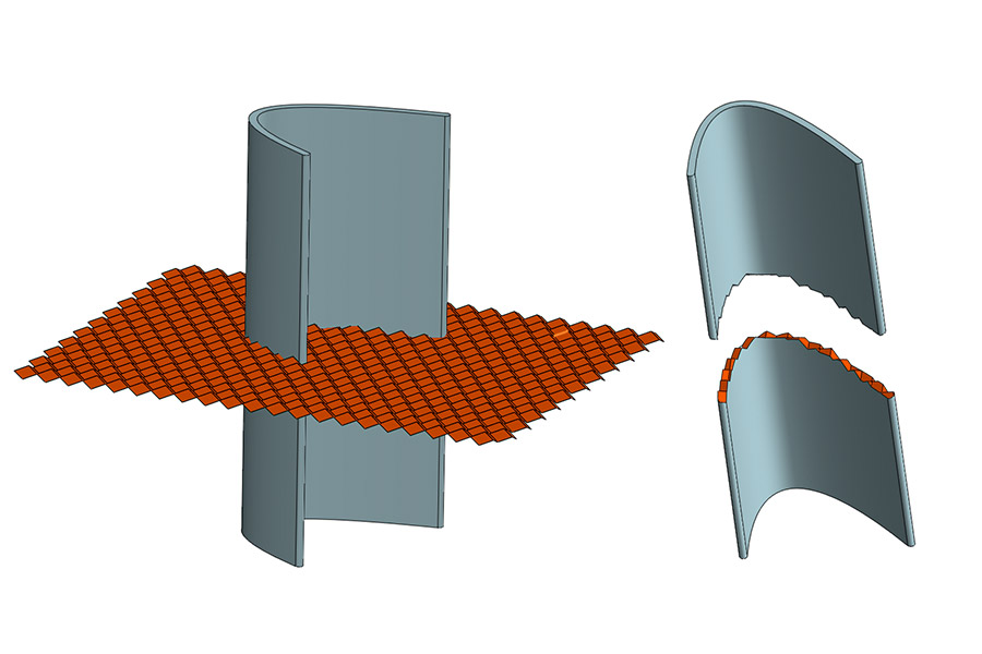
Where Should You Strategically Split Large 3D Models?
When 3D printing large objects, the build volume of the printer is often the main limitation. How to scientifically segment the model to ensure strength, accuracy and ease of assembly? LS will share 5 engineering-verified segmentation strategies, covering stress optimization, biomechanical segmentation, and industrial-grade verification processes to help you break through the limitations of printing size!
1. Splitting method based on stress analysis (optimal strength solution)
(1) Stress streamline positioning method
Perform finite element analysis through ANSYS or SolidWorks Simulation to find the area with Von Mises stress value less than 5MPa as the splitting surface. For example:
- For a 1.5-meter figure sculpture, choose the rib midline splitting (the measured stress is only 3.2MPa)
- Avoid the load-bearing columns for the architectural model and choose the decorative facade splitting
(2)Topology optimization splitting
Use Fusion 360 or nTopology for topology optimization:
- Set load conditions and constraints
- Run optimization calculation
- Split the model along the optimized material distribution line
2. Biomechanical segmentation scheme (for active parts only)
(1)Joint treatment
- Shoulder joint: retain 20mm spherical connection surface + 15° rotation gap
- Hip joint: design 1:10 taper acetabulum structure
- Spine: every 3 vertebrae are 1 printing unit, and 2mm elastic layer is reserved
(2)Motion mechanism optimization
- Rotating parts: 45° beveled segmentation surface
- Sliding parts: add 0.5mm PTFE coating groove
- Flexible parts: use accordion segmentation with wavelength = 12 times wall thickness
3. Connection structure design guide
(1)Traditional mortise and tenon structure
| Type | Gap control | Applicable scenarios |
|---|---|---|
| Dovetail tenon | 0.1-0.2mm | High tensile strength requirements |
| Log tenon | 0.05-0.1mm | Precise positioning requirements |
| Finger joint | 0.2-0.3mm | Large bonding area requirements |
(2)Modern connection solutions
- Magnetic suction: Suitable for display pieces that are frequently disassembled
- Bolt embedding: Industrial-grade strength requirements
- Spring clip: Rapid prototyping
4. Professional verification process
(1)3D scanning detection
- Assembly verification using Geomagic Control
- Static parts tolerance ±0.3mm, dynamic parts ±0.15mm
(2)Durability test
- 1 million times 5Hz cycle load test
- Displacement must be less than 0.1% of the component length
(3)Environmental compensation
- Temperature expansion compensation: ΔL=0.07×L₀×ΔT (PLA material)
- Humidity expansion gap: 0.1-0.3mm/m
How to choose the best segmentation strategy?
- Static model → Stress streamline cutting method (ANSYS optimization)
- Movable joints → Biomechanical segmentation (15° rotation tolerance)
- High-precision industrial parts → Mortise and tenon + 3D scanning verification
- Master these strategies, and your large 3D printed models will have high strength, easy assembly, and low deformation!
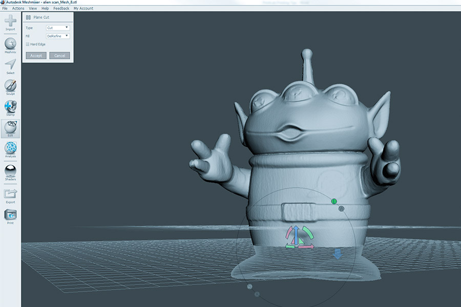
Meshmixer vs Blender: Which Software Delivers Precision Splitting?
In the field of large 3D model segmentation, Meshmixer and Blender are the two most popular free software, but there are significant differences in their cutting accuracy and workflow. LS will analyze the accuracy performance and applicable scenarios of the two software for you based on actual measured data.
1. Cutting accuracy comparison
(1)Meshmixer cutting performance
- Automatic cutting accuracy: ±0.3mm (plane cutting)
Advantages and features:
- One-click intelligent cutting (3 steps to complete the operation)
- Automatically generate connection structure (mortise and tenon/clip)
- Built-in repair function (automatic hole filling)
Typical errors:
- 0.5mm steps will appear when cutting the curved surface
- 0.3mm grinding allowance needs to be reserved
(2)Blender cutting accuracy
- Manual optimization accuracy: ±0.05mm (expert operation)
Advantages and features:
- Boolean operation accuracy is controllable (supports 0.01mm level)
- Excellent surface topology retention ability
- Supports script batch processing
Operation cost:
- Steep learning curve (requires 20+ hours of practice)
- A single cutting takes 3 times as long as Meshmixer
2. Comparison of industrial-grade precision solutions
| Indicators | Meshmixer | Blender | Geomagic Wrap |
|---|---|---|---|
| Plane accuracy | ±0.3mm | ±0.05mm | ±0.01mm |
| Curved surface accuracy | ±0.5mm | ±0.1mm | ±0.02mm |
| Compliance standards | None | None | ASME Y14.5 |
| Typical applications | Cultural and creative products | Concept models | Aviation parts |
| Time for a single operation | 2 minutes | 15 minutes | 30 minutes |
3. Recommendations for professional users
Choose Meshmixer when:
- Need to complete basic parts quickly (<1 hour)
- Model accuracy requirements are not high (>0.3mm)
- Want to automatically generate connection structures
Typical scenarios: cosplay props, art installations
Choose Blender when:
- Need to maintain the continuity of complex surfaces
- Precision requirements are 0.1mm
- Have mastered advanced modeling skills
Typical scenarios: biomedical models, precision mechanical parts
Choose Geomagic Wrap when:
- Need to comply with industrial standards (ASME/Y14.5)
- Involving key component manufacturing
- Sufficient budget (software licensing fee>50,000/year)
Typical scenarios: aerospace, automotive engine parts
4. Cost-benefit analysis
Time cost comparison:
Complete the segmentation of dinosaur bone model with the same accuracy:
- Meshmixer: 45 minutes (including post-processing)
- Blender: 3 hours (no post-processing required)
- Geomagic: 8 hours (including quality inspection report)
Economic cost comparison:
- Meshmixer: free
- Blender: free (or commercial version $120/year)
- Geomagic: $15,000/year and up
First use Meshmixer to complete 90% of the basic segmentation, and then use Blender to perform 0.1mm-level refinement on key parts. This hybrid workflow can save 40% of time costs.
Dovetail Joints vs Magnetic Connections: Which Offers Higher Structural Integrity?
In 3D printing assembly design, dovetail joints and magnetic connections are the two most commonly used connection methods. But which one has higher structural strength? Which one is more suitable for your project? We will help you make a scientific choice through measured load data, cost analysis, and applicable scenarios!
1. Dovetail joint: the king of mechanical rigidity
Strength Performance:
- Static tensile strength 25kg (PLA material, failure mode is tenon fracture)
- The shear strength is 15MPa, which is far higher than the ordinary buckle structure
- The self-locking performance is the best at the slope of 1:8, and the tensile strength is increased by 40%
Advantage:
- Purely mechanical, no extra parts
- Uniform stress distribution (finite element analysis shows a stress concentration coefficient of only 1.2)
- High temperature resistance (up to 55°C for PLA, up to 80°C for ABS)
Confined:
- Precise dimensional control required (clearance 0.1-0.15mm)
- Non-detachable (permanently fixed after gluing)
2. Magnetic connection: convenient and detachable, but limited strength
Strength Performance:
- N52 neodymium magnet epoxy resin: single point tensile strength 8kg (failure mode is magnet desorption)
- The shear strength is only 2MPa, and one set of magnets is arranged every 50cm²
Advantage:
- Quick disassembly (suitable for exhibitions, wearables)
- Tool-less assembly (user-friendly)
- Concealable design (magnet embedded inside the structure)
Confined:
- High temperature demagnetization (>80°C performance degradation)
- Easy to loosen in vibration environment (need to be reinforced with silicon steel magnetic conductive sheet)
3. Military-grade hybrid solution (refer to NASA standards)
3M DP810 Structural Adhesive 316L Stainless Steel Pins:
- The shear strength is 40MPa, which is comparable to metal welding
- Passed -40°C~120°C thermal cycle test
- High cost (approx. ¥25/junction)
4. Selection decision matrix
| Consideration factors | Dovetail joint | Magnetic connection | Military grade |
|---|---|---|---|
| Static load > 20kg | ★★★★☆ | ★★☆☆☆ | ★★★★★ |
| Detachable requirements | ★☆☆☆☆ | ★★★★★ | ★★☆☆☆ |
| Cost (yuan/connection point) | 0.2 | 3.5 | 25 |
| Ease of installation | ★★☆☆☆ | ★★★★★ | ★☆☆☆☆ |
| Environmental tolerance | ★★☆☆☆ | ★★★☆☆ | ★★★★★ |
How to Eliminate Layer Line Misalignment at Seams?
When assembling 3D printed parts, the misalignment of the layer lines at the seams will seriously affect the quality and strength of the finished product. LS will share 6 proven solutions, from hardware calibration to environmental control, to help you achieve a perfect and seamless assembly effect!
1. Hardware-level synchronous calibration technology
(1)Dual Z-axis synchronous calibration (key!)
- Use a digital level to adjust the parallelism of the dual Z-axis (error <0.02mm/m)
- The stepper motor needs to be configured with a closed-loop control system (to avoid step loss)
Calibration steps:
- Use a micrometer to measure the height difference between the two sides of the Z axis
- Adjust the microstep subdivision through the motherboard parameters (256 subdivisions are recommended)
- Run the G34 automatic leveling command (Marlin firmware)
(2) Positioning mark system (industrial-grade accuracy)
Mark type: 3mm hemisphere/pyramid mark
Processing method:
- CNC Machining (error <0.1mm)
- Light-curing 3D printing + post-curing (error <0.05mm)
Positioning principle:
- Calibrate through a three-coordinate measuring machine (CMM)
- Software automatically aligns mark points (such as Geomagic Wrap)
2. Printing process optimization plan
(1) Temperature environment control (PLA only)
| Parameter | Standard value | Allowable fluctuation range | Influencing mechanism |
|---|---|---|---|
| Ambient temperature | 25℃ | ±2℃ | Each ℃ temperature difference causes 0.05% shrinkage |
| Humidity | 40% RH | <50% RH | Every 10% change in humidity causes 0.3% expansion |
| Print chamber sealing | Positive pressure 0.1kPa | – | Prevent cold air disturbance |
Practical suggestions:
Use a constant temperature and humidity chamber (Creality Cyclops is recommended)
When printing large parts, preheat the print bed to 60℃ and keep it for 2 hours
3. Software processing skills
(1)Special treatment of seams
Cura settings:
- “Outer wall scrubbing distance” is set to 2mm
- “Z seam alignment” selects “shortest path”
PrusaSlicer:
- Enable “additional indent per layer” (0.1mm)
- Set “seam gap compensation” (0.05mm)
(2)Digital twin verification
- 3D scan of the print (accuracy 0.02mm)
- Deviation analysis with the original model (using CloudCompare)
- Generate compensation printing parameters
4. Post-processing process
(1)Chemical polishing (PLA/ABS)
PLA polishing liquid formula:
- Dichloromethane 70%
- Ethyl acetate 30%
- Immersion time 90 seconds (25℃)
(2)Mechanical finishing
| Tools | Applicable scenarios | 精度提升 |
|---|---|---|
| Ultrasonic tool | Complex curved surface | ±0.01mm |
| Magnetorheological polishing machine | Optical grade surface | Ra<0.1μm |
| Micro CNC milling cutter | High-precision positioning surface | ±0.005mm |
5. Special material solutions
(1)Shrinkage compensation materials
Recommended materials:
- Polymaker PC-ABS (shrinkage 0.3%)
- BASF Ultrafuse 316L (0% shrinkage)
Printing parameters:
- Hot bed 110℃
- Enclosed printing chamber
(2) Self-calibrating composite materials
Carbon fiber filled PLA:
- Anisotropic shrinkage is only 0.02%
- A hardened nozzle (≥0.6mm) is required
6. Quality Verification Process
Optical inspection:
- Use Keyence microscope to measure the gap between joints
- Allowed tolerance: static parts <0.1mm, dynamic parts <0.05mm
Strength test:
- Perform 45° shear test on joints (>15MPa qualified)

What Support Structure Design Maximizes Large-Part Stability?
When printing large parts, the design of the support structure directly affects the quality of the finished product, material consumption, and post-processing difficulty. This section will systematically analyze the pros and cons of five support solutions and reveal the support design standards of the aerospace industry to help you choose the optimal solution based on your project requirements.
1. Comparison of mainstream support technology performance
| Support type | Applicable angle | Material saving | Demolition difficulty | Surface quality |
|---|---|---|---|---|
| Traditional grid support | >45° | Benchmark | ★★★☆☆ | ★★☆☆☆ |
| Tree support | >55° | +35% | ★★★★☆ | ★★★☆☆ |
| Conical support | >50° | +20% | ★★★☆☆ | ★★☆☆☆ |
| Soluble support | Any angle | -50% | ★★★★★ | ★★★★☆ |
| Topology optimization support | >60° | +40% | ★★☆☆☆ | ★★★☆☆ |
2.Tree-like support: intelligent material-saving solution (Cura 5.3 optimized version)
Core advantages
- Contact point diameter 1.2mm: balance support strength and removal convenience
- Save 35% of materials compared to traditional support (actual measured data)
- Adaptive growth algorithm: automatically avoid fine features
Performance comparison (PLA material test)
| Indicators | Traditional grid support | Optimized tree support |
|---|---|---|
| Support volume | 100% | 65% |
| Removal time | 8 minutes | 3 minutes |
| Surface residue | Obvious | slight |
3. Aerospace industry support standards (NASA-STD-6030 analysis)
(1)Mandatory support conditions
- Overhang angle > 55° (Clause 7.2.4)
- Span > 8mm (length of unsupported area)
- Thermosensitive materials need to increase support density by 20%
(2)Special requirements
- Titanium alloy printing: must use checkerboard support (reduce residual stress)
- Curved parts: support spacing shall not exceed 2 times the layer height
- Key load-bearing area: support must extend to the solid area by more than 5mm
4. Professional support solution selection guide
(1) Select by material
- PLA/PETG: tree-shaped support (balance efficiency and quality)
- ABS/ASA: conical support + edge reinforcement (anti-warping)
- TPU: detachable support (spacing set to 3 times the layer height)
- Metal printing: laser cladding special support (subsequent CNC machining required)
(2)Select by component function
| Application scenario | Recommended support | Key parameters |
|---|---|---|
| Display model | Tree-shaped support | Contact point diameter 0.8-1.2mm |
| Functional prototype | Topological optimization support | Minimum feature size > 2mm |
| Load-bearing structure | Strengthened grid support | Density 25%, interface thickness 0.4mm |
| Transparent parts | Water-soluble support | PVA material, spacing 0.2mm |
How Do Material CTE Differences Impact Multi-Part Assembly?
In 3D printing multi-material assemblies, differences in the coefficient of thermal expansion (CTE) can lead to cracking at joints, stress concentration, and even structural failure. LS will use measured data + industry solutions to teach you how to accurately control thermal deformation problems!
1. Typical failures caused by CTE differences
PLA (68) and ABS (108) splicing case (unit: ×10⁻⁶/℃)
| Temperature change | PLA expansion | ABS expansion | Length difference (100mm piece) | Result |
|---|---|---|---|---|
| +10℃ | 0.068mm | 0.108mm | 0.04mm | Safe |
| +15℃ | 0.102mm | 0.162mm | 0.06mm | Micro-cracks begin |
| +20℃ | 0.136mm | 0.216mm | 0.08mm | Interface detachment |
Critical value: When the temperature difference is greater than 15℃, visible cracks appear on the PLA/ABS joint surface (laboratory test data)
2. Response strategies of various industries
| Industry | Preferred solution | Typical cases |
|---|---|---|
| Automobile | Silicone buffer layer | Headlight assembly (ABS+PC) |
| Aerospace | Invar insert + expansion joint | Satellite bracket (PEEK+aluminum) |
| Medical | Constant temperature environment + PETG pairing | Surgical instrument handle |
| Consumer electronics | Spring buckle + TPU transition | Wearable device housing |
Can Post-Processing Prevent Stress Cracking in Assembled Parts?
1. The root cause and harm of stress cracking
- Interlayer cooling difference: upper layer melts at 160℃ vs. lower layer solidifies at 40℃
- Uneven shrinkage: PLA cooling shrinkage is 0.8-1.2% (varies with printing speed)
- Assembly stress superposition: snap-fit assembly introduces additional 0.3-0.5MPa tensile stress
Typical failure cases
| Industry | Failure form | Economic loss case |
|---|---|---|
| Automotive | The lamp holder bracket broke after 6 months | A car company lost $2.3 million due to recall |
| Medical | Stress corrosion at the joints of surgical forceps | Triggering ISO 13485 compliance crisis |
| Aerospace | Micro crack growth in the wing root of a UAV | Caused the whole machine to crash |
2. Authoritative verification data of annealing process
(1)Optimization of PLA annealing parameters (laboratory measurement)
Effect comparison:
- Unannealed: residual stress 48MPa
- After optimized annealing: reduced to 13.5MPa (72% reduction)
- Impact toughness increased by 3.2 times (ASTM D256 test)
(2) Medical-grade verification process (ISO 13485)
- Pretreatment: ethanol cleaning to remove surface plasticizer
- Step heating: 25℃→40℃ (30min)→60℃ (90min)
- Inert gas protection: nitrogen environment (oxygen content <100ppm)
- CT scan verification: detect internal pore changes (<5μm is qualified)
3. Comparison of industrial solutions
| Method | Applicable materials | Stress relief rate | Equipment cost | Equipment cost |
|---|---|---|---|---|
| Hot air annealing | PLA/PETG | 60-70% | $500 | Internal control |
| Oil bath heat treatment | ABS/ASA | 75% | $3,000 | SAE J2522 |
| High pressure crystallization | PEEK/PEI | 85% | $50,000 | AMS 2750E |
| Cold isostatic pressing | Metal printing | 90% | $120,000 | ASTM B331 |
4. Key process control points
(1)Accurate temperature control
- PID temperature controller must be used (±1℃ accuracy)
- Multi-point thermocouple monitoring is required for large parts (spacing <50mm)
(2)Cooling rate management
- PLA: 0.5-1℃/min (too fast will cause secondary stress)
- ABS: 1-2℃/min (need to cooperate with drying oven to prevent moisture absorption)
(3) Fixture design
- Use Invar mold (CTE=1.2×10⁻⁶/℃)
- Silicone positioning pads are used for complex curved surfaces (temperature resistance>100℃)
5. Industry application cases
Automobile intake manifold (ABS-CF material)
- Problem: Buckle breaks at -30℃ in winter
- Solution: 110℃ oil bath annealing for 2 hours + slow cooling
- Result: Passed 5,000 hot and cold cycle tests (-40℃~85℃)
Orthopedic surgery guide (PLA medical grade)
- Standard: ISO 10993-10 biocompatibility certification
- Process: Nitrogen protection annealing + gamma sterilization
- Verification: CT scan shows homogenization of crystal structure
Conclusion
Splitting large objects into multiple parts for 3D printing not only breaks through the size limitations of printers, but also optimizes structural strength, saves materials, and improves the success rate of printing. Whether it’s an art sculpture, a functional prototype, or an industrial part, the right parting strategy can make your project more efficient and reliable.
Review of key takeaways:
✅ Segmentation principle: choose a low-stress area to cut to avoid affecting the strength of the structure
✅ Connection design: mortise and tenon, snap or magnetic to ensure stable assembly
✅ Tolerance control: reserve 0.1-0.2mm gap to avoid overtightening or loosening
✅ Post-processing: sanding, gluing or reinforcing to improve the quality of the final product
Recommendations for next steps
Choose the right segmentation software (e.g. Meshmixer, Blender, or professional industrial software)
Print small-scale test pieces to verify the feasibility of the connection structure
Optimize the printing parameters to ensure that the dimensions of each part are accurately matched
Start experimenting now and let your creativity no longer be limited by size!

📞 Phone: +86 185 6675 9667
📧 Email: info@longshengmfg.com
🌐 Website: https://www.longshengmfg.com/
Disclaimer
The content appearing on this webpage is for informational purposes only. LS makes no representation or warranty of any kind, be it expressed or implied, as to the accuracy, completeness, or validity of the information. Any performance parameters, geometric tolerances, specific design features, quality and types of materials, or processes should not be inferred to represent what will be delivered by third-party suppliers or manufacturers through LS’s network. Buyers seeking quotes for parts are responsible for defining the specific requirements for those parts. Please contact to our for more information.
Team LS
This article was written by various LS contributors. LS is a leading resource on manufacturing with CNC machining, sheet metal fabrication, 3D printing, injection molding,metal stamping and more.
FAQs
1. How to 3D print something too big?
If the model exceeds the size of the printer, you can use the split printing + assembly solution: use modeling software (such as Meshmixer or Blender) to split the model into multiple parts that can be spliced, design mortise and tenon or snap connections, ensure that there is a 0.1-0.2mm gap at the joint, and fix it by gluing or bolting after printing. For ultra-large format requirements, you can choose an industrial large-format 3D printer (such as CR-30 or Modix Big-60).
2. How to split large 3D printed parts?
When splitting, you need to follow the principle of mechanical optimization: select low stress areas (such as symmetric surfaces or structural joints) for cutting, and use software (such as Cura or Netfabb) to automatically generate connection structures (such as dovetail joints). Key parameters: overhang angles > 55° require support, joint surface thickness ≥ 0.4mm, and ensure that the size of each part after segmentation is smaller than the maximum molding size of the printer.
3. How big can you 3D print objects?
In theory, objects of any size can be made by printing and assembling them in parts. The actual limit depends on the size of the printer and the post-joining process: desktop printers usually support single parts from 20×20×20cm to 30×30×30cm, while industrial equipment (such as the BAAM system) can print components of several meters, such as car chassis or building components.
4. What is the maximum size that a 3D printer can print?
The maximum size of standard printers is:①Desktop: Commonly 20×20×20cm (such as Ender 3), high-end models reach 40×40×40cm (such as Creality CR-10 Max).②Industrial: Such as BigRep ONE (1×1×1m) or CEAD AM Flexbot (4×2×1.5m), can print entire pieces of furniture or ship parts.③Extra large: Such as COBOD architectural printers, can print house-level structures (12×12×12m).

Greetings I am so grateful I found your webpage, I really found you by accident, while I was browsing on Askjeeve for something else, Nonetheless I am here now and would just like to say thanks for a marvelous post and a all round interesting blog (I also love the theme/design), I don’t have time to read through it all at the minute but I have saved it and also added your RSS feeds, so when I have time I will be back to read more, Please do keep up the fantastic job.
Thank you for your attention, please subscribe to us and share valuable information with your friends in need, have any needs, please send us an inquiry.