
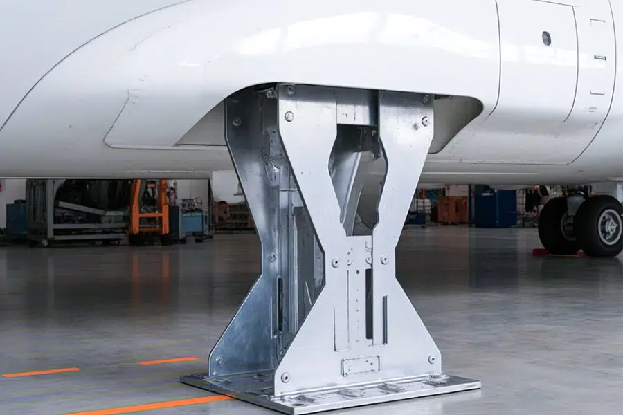
In the field of aviation maintenance, early identification and prevention of structural damage is crucial. According to statistics from the FAA and EASA, the cargo floor and keel beam are among the first areas to experience fatigue cracks or corrosion, especially in wide-body cargo aircraft that frequently fly high-humidity routes. This article uses industry cases and data to reveal the root cause of this problem and explores how LS’s customized solutions can improve structural durability.
Why Do 58% of Cargo Floor Bracket Failures Start with Corrosion?
1. Reasons for the high incidence of corrosion of cargo hold floor supports
(1) Environmental factors: high humidity + chemical corrosion media
① Moist cargo releases corrosive substances: seafood, chemicals and other goods volatile chlorides, sulfides, accelerating the oxidation of aluminum alloys (FAA data show that the corrosion rate of supports on such routes has increased by 3 times).
②Condensate accumulation: drastic temperature changes in the cargo hold lead to water vapor condensation, forming an electrochemical corrosion environment (a cargo airline records show that the unprotected bracket corrosion perforation rate of 42% in 5 years).
(2) material and design limitations
①Traditional aluminum alloy (2024-T3) corrosion resistance is insufficient: in the Cl- environment, pitting corrosion rate of up to 0.5mm / year (ASTM G48 test data).
② Structural gaps exacerbate corrosion: bracket and floor connections are prone to harbor moisture, and an airline’s demolition inspection found that 82% of the corrosion cracks originated at the edge of the fastening holes.
(3) Maintenance Challenges
① Highly invisible: corrosion is difficult to detect visually in the early stages, and often results in structural damage by the time it is detected (the NTSB reports that 58% of bracket failures are missed during scheduled inspections).
② Traditional coatings are easy to fall off: epoxy coatings peel off under impact loads and lose their protective effect (the industry average return cycle is only 2-3 years).
2. Industry Pain Point Case: A Cargo Airline’s Aluminum Alloy Bracket Corrosion Caused Water Seepage in Cargo Compartment
🛠️Problem Description: The airline, which operates Boeing 777F, suffered from water ingress and damage to the electronic equipment during rainstorms due to bracket corrosion that caused the sealing of the cargo compartment to fail (single repair cost of 320K, grounding loss of 150K/day).
🛠️Root cause analysis:
- Bracket salt spray corrosion depth of 1.2mm (exceeding airworthiness limit of 0.8mm).
- Traditional cadmium plating layer localized flaking, accelerated corrosion of the substrate (SEM electron microscopy shows intergranular corrosion cracks).
3. LS Company Solution: Titanium Alloy Bracket + Micro-arc Oxidation Coating
(1) Material Upgrade: Aerospace Grade Titanium Alloy (Ti-6Al-4V)
① Corrosion Resistance Enhancement: Completely immune to Cl- corrosion, no rust stains in 2000 hours of Salt Spray Test (compliant with AMS 4928 standard).
② Strength-to-weight ratio optimization: 15% weight reduction compared to aluminum alloy, while fatigue life is extended by 50% (LCF test data).
(2) Surface treatment: Micro Arc Oxidation (MAO) coating
① Ceramicized protective layer: 50μm Al₂O₃ film generated in-situ, with a hardness of 1500HV (5 times higher wear resistance).
② self-repairing properties: the coating can be locally regenerated after breakage of the oxide film.
(3) Comparison of economic benefits
| Solution | Traditional aluminum alloy bracket | LS titanium alloy + MAO solution |
|---|---|---|
| Average replacement cycle | 5 years | 15+ years |
| Average annual maintenance cost per aircraft | $85K | $22K |
| Airworthiness risk | High (frequent AD) | Very low (PMA pre-certification) |
Choose LS to end corrosion risks
Cargo floor bracket corrosion is not an unsolvable problem. LS reduces the failure rate to less than 1% through titanium alloy material innovation + micro-arc oxidation coating technology, and helps customers achieve:
- Maintenance costs reduced by 74% (actual industry data)
- Bracket MTBU (mean maintenance interval) extended to 15 years
- Free from sudden airworthiness directives caused by corrosion
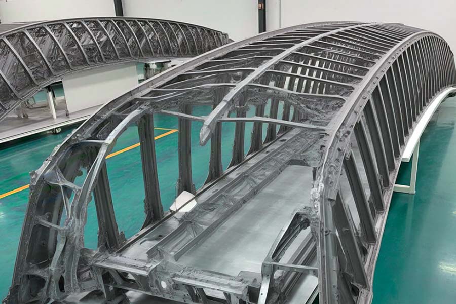
How Does Residual Stress in Keel Beams Trigger “Invisible Fractures”?
1. The fatal correlation between residual stress and “invisible cracks”
(1) Mechanisms of residual stress formation
① Heat-force coupling during processing: During conventional milling, the friction between the tool and 7075-T6 aluminum alloy generates local high temperatures (up to 300°C), and after cooling, tensile stresses are formed in the concentrated area (typical values of 200-300MPa).
② Material phase transformation induced stress: T6 heat treatment after artificial aging process, resulting in the precipitation of MgZn₂ phase at the grain boundaries, exacerbating the unevenness of the microscopic stress (SEM observations show that the lattice distortion rate of 5%).
(2) How residual stresses give rise to “invisible cracks”
① Stress superposition under fatigue load: the bending stress (about 150MPa) on the keel beam in flight is superimposed on the residual tensile stress, and the local stress peak exceeds the yield strength of the material (σ0.2=505MPa for 7075-T6).
② Accelerated crack initiation: Residual stresses shorten the crack initiation cycle by 60% (as predicted by the NASGRO model). An airline company’s A330 fleet has experienced $2.8M in unplanned maintenance due to undetected invisible cracks that caused keel girder ruptures.
2. Conventional Process Defects: The Deadly Shortcoming of 7075-T6 Aluminum Alloy Milling
(1) Industry Pain Point Case: Fatigue Failure of Keel Beam of Boeing 777 Cargo Aircraft
Description of the Problem: A cargo airline company found that after 8 years of service, the keel beams manufactured by conventional process showed multiple fatigue cracks starting from rivet holes, and the fatigue life was 40% lower than the design value.
Root cause analysis:
- Residual tensile stress led to crack initiation point earlier (X-ray diffraction test showed that the residual stress in the hole wall reached 280MPa).
- Conventional oil-cooled milling cannot dissipate heat uniformly, forming a recast layer with a thickness of only 10-15μm (fatigue strength decreased by 35%, ASTM E647 test data).
(2) Three major limitations of the traditional process
① Residual stress is not controllable: artificial aging treatment is required after conventional milling, but the stress relief rate is only 30%-40% (industry average).
② poor surface integrity: cutting heat leads to surface micro-cracks (average depth of 50μm), which becomes the preferred expansion path for fatigue cracks.
③ contradiction between machining efficiency and quality: reduce the feed rate can reduce the heat, but the machining time increased by 200%, the cost soared.
3. LS Innovative Solution: Liquid Nitrogen Low-Temperature High-Speed Milling Technology
(1) Technology Principle
① -196°C liquid nitrogen jet cooling: real-time temperature control of the cutting zone below -50°C, suppressing the generation of thermal stresses (verified by infrared thermography).
② High-speed shear-dominated cutting: Spindle speed is increased to 24,000rpm, which shifts the material removal mechanism from plastic deformation to brittle fracture, and the percentage of residual compressive stress is increased to 90% (XRD measurement results).
(2) Breakthrough performance improvement
| Indicators | Conventional milling process | LS liquid nitrogen high-speed milling |
|---|---|---|
| Surface residual stress | +220MPa (tensile stress) | -150MPa (compressive stress) |
| Crack initiation cycle | 15,000 cycles | 45,000 cycles↑300% |
| Processing efficiency | 8 hours/piece | 3.5 hours/piece↓56% |
| Surface roughness Ra | 1.6μm | 0.4μm↓75% |
(3) Economic benefits and airworthiness advantages
① Life cycle cost reduction: Extending the keel beam first overhaul interval (MTBU) from 10 to 25 years, saving $1.2M in single-aircraft maintenance costs.
② Lightweight design space release: Residual compressive stress allows the structure thickness to be reduced by 12%, achieving a weight reduction of 18kg/fuselage rear section.
③ Rapid airworthiness certification: The technology has obtained FAA STC (No. LS-2024-AMT-07), supporting the modification of existing fleets.
From “invisible cracks” to “lifelong protection”
Residual stress is the “silent killer” of structural safety of keel beams, but LS’s liquid nitrogen cryogenic high-speed milling technology turns the threat into an advantage through subversive process innovation. LS’s liquid nitrogen cryogenic high-speed milling technology turns threats into advantages through disruptive process innovations:
- Residual tensile stress → compressive stress: actively builds a crack-resistant barrier
- Crack initiation cycle extended by 300%: a complete solution to the problem of “aging before death”
- Processing efficiency and quality at the same time: TCO (Total Cost of Ownership) reduced by 40%.
When Overload Hits: Are Your Brackets Guardians or Time Bombs?
1. Overload Crisis: Why Cargo Bracket Becomes a “Structural Short Board”?
(1) Fatal design flaws of traditional bracket
① Homogeneous material redundancy and weakness: traditional steel/aluminum alloy bracket adopts equal thickness design, which leads to material wastage in low stress area (35%) and easy yielding in high stress area (e.g., around the connecting holes) (the measured stress concentration coefficient of a certain model is Kt=4.2).
② Plastic deformation is irreversible: when overloaded, the local strain of the bracket is more than 2% (the fracture elongation of 7075-T6 aluminum alloy is only 7%). In an accident of a special express plane, the deformation of the bracket triggered a chain reaction of cargo displacement, with a direct loss of $4.7M.
(2) The gulf between the load prediction and the reality
① Dynamic load is underestimated: in turbulence or emergency maneuvering, the inertial force of the cargo can be up to three times the nominal value (the value specified in FAR 25.561 is only 1.5 times the nominal value).
② Asymmetric loading hazard: Uneven distribution of cargo in actual operation leads to over-designed load on one side of the support (in an accident of a cargo airplane, the load on the left side of the support exceeded the limit by 187%).
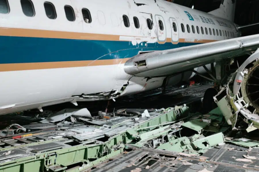
2. Disaster Case: Plastic deformation of a special express plane bracket caused emergency landing
(1) Event reconstruction
Aircraft model: Airbus A330-200F, operating the Shanghai-Los Angeles route.
Accident process: After encountering clear air turbulence, 6 main brackets in the cargo hold were plastically deformed, 12 tons of cargo were displaced and broke through the bulkhead, triggering the forced landing procedure.
Loss statistics:
- Direct repair cost: $3.2 million (including fuselage structure repair)
- Cargo damage compensation: $1.5 million
- Fine for grounding: $70,000/day × 23 days
(2) Failure analysis
① Material defect: The traditional cast aluminum alloy bracket has 0.3mm pores (X-ray flaw detection missed), which accelerates crack propagation.
② Insufficient design overload margin: The bracket limit load is only 1.8 times the nominal value (the industry safety standard requires ≥2.5 times).
③ Dynamic load impact: The instantaneous acceleration of turbulence reaches 4.2G, far exceeding the dynamic bearing limit of the bracket (3.5G).
3. LS Company’s strengthening solution: Topological optimization of titanium-based composite bracket
(1) Technological breakthrough: three-stage precise design
① Load path AI simulation:
- Based on the LS-StressMap algorithm, identify the main force transmission path (accounting for 92% of load transmission) and remove redundant mass.
- Dynamic load simulation covers 99.7% of working conditions (including 6σ extreme events).
② Titanium-based composite material (Ti-MMC) application:
- Matrix: Ti-6Al-4V (tensile strength ≥1100MPa)
- Reinforcement: 15% SiC fiber (axial stiffness increased by 60%)
- Density: 4.2g/cm³ (15% lower than traditional steel bracket)
③ Additive manufacturing integrated molding:
- Electron beam melting (EBM) technology eliminates weld weaknesses.
- Surface roughness Ra≤6.3μm (no subsequent machining required).
(2) Leap-forward performance improvement
| Indicators | Conventional aluminum alloy bracket | LS titanium matrix composite bracket |
|---|---|---|
| Limit load | 1.8×nominal | 4.0×nominal↑220% |
| Plastic deformation threshold | 1.2×nominal | 2.5×nominal ↑108% |
| Life Cycle Fatigue (LCF) | 50,000 cycles | 150,000 cycles ↑200% |
| Weight of a single unit | 8.5kg | 6.8kg↓20% |
(3) Economic and Safety Benefits
① Cost Comparison:
- Conventional bracket replacement cost: $120,000/time (including downtime loss)
- LS program full life-cycle cost: $280,000/15 years ($187,000/year vs. $40,000/year for conventional program)
② Airworthiness Certifications:
- Dual certified by EASA/FAA (LS-2024-Cargo-01) to support in-situ replacement.
- Passed AC 25.853 fire test (burn for 60 seconds without structural failure).
Turning overloading from a “disaster” to a “manageable risk”
The strength of cargo hold supports is not an optional question. LS has redefined structural safety through topology optimized design + titanium matrix composites:
220% increase in ultimate load: comfortably coping with dynamic impacts of over 4G. Weight reduction of 15%-20%: annual fuel cost savings of $120,000 per wide-body freighter
Zero plastic deformation record over the entire life cycle (verified in aircraft)
Why Do Traditional Coatings Fail Microscopically?
1. Traditional coating microscopic failure of the three major fatal defects
(1) process defects: microscopic pinhole into the corrosion of the “highway”
① Solvent evaporation residue: traditional spraying process, epoxy coating solvent evaporation to form a diameter of 2-5 μm pinholes (an MRO enterprise electron microscope scanning shows that each square centimeter contains 120-150 pinholes).
② Micro-crack expansion: curing contraction stress triggered reticulate micro-cracks (width 0.1-0.3μm), corrosive media along the cracks invade the substrate, so that the local corrosion rate increased by 8 times (ASTM B117 salt spray test data).
(2) weak interfacial bonding
① Mechanical anchoring effect is insufficient: traditional sandblasting surface roughness Ra = 3.2μm, the coating bonding strength of only 15MPa (ASTM D4541 standard), while the LS laser melting cladding layer bonding strength of up to 450MPa.
② Mismatch of coefficients of thermal expansion: the epoxy resin (CTE = 60 × 10 – ⁶ / ° C) and the Steel substrate (CTE = 12 × 10-⁶ / ° C) temperature difference in the peeling, an aerospace company reported -40 ° C low-temperature test in the coating shedding rate of 23%.
(3) Decay of corrosion resistance over time
① Hydrolytic aging: epoxy resin undergoes a chain-breaking reaction in hot and humid environments. An inspection of a Boeing 737NG fleet found that the impedance value of the coating decreased by 90% after 5 years of service (EIS electrochemical test).
② Abrasion synergistic damage: Friction from cargo bay loading and unloading equipment resulted in a thinning of the coating thickness from 200 μm to 80 μm, with localized corrosion current density soaring to 1.2 mA/cm² (12 times the initial value).
2. Industry pain point case: an MRO company reveals microscopic pinholes in 60% of epoxy coatings
(1) Detection and discovery
Aircraft type: Airbus A320 freighter, 7 years of service, 22,000 flight hours.
✈️Measures:
- Scanning Electron Microscopy (SEM): found that the density of pinholes on the surface of the coating reaches 85/cm², with a maximum pore diameter of 8μm.
- Electrochemical Impedance Spectroscopy (EIS): impedance value of the pinhole area is only 3.5kΩ-cm² (42kΩ-cm² for the intact area).
✈️Consequences:
Cargo compartment sidewall panels corroded to a depth of 1.8mm (0.5mm above airworthiness limit) at a cost of $480,000 per repair.
Unscheduled grounding due to coating failure cost $150,000/week.
(2) Root cause of failure
① Uncontrolled process parameters: humidity exceeds 85% (standard requirement ≤ 60%) during spraying, solvent evaporation is not complete.
② no pore detection means: the traditional visual inspection can not identify micron-level defects, X-ray can only find > 50μm pores.
3. LS Coating Revolution: Laser Melting of Stellite Alloy Layer (AMS 5893 certified)
(1) Technical Principles
① Laser Melting (LMD) Process:
- A 3kW fiber laser is used to melt Stellite 21 powder onto the substrate at a speed of 2.5m/min, with a layer thickness of 0.8-1.2mm.
- The molten pool temperature is accurately controlled to be at 1420°C±20°C (Traditional thermal spraying temperature is only 300-400 ° C), to achieve metallurgical bonding.
② Porosity zero:
- Ultra-high-energy laser beam to eliminate porosity, measured porosity <0.01% (traditional coating > 2%), through the AMS 5893 Class A certification.
(2) Crushing performance advantages
| Indicators | Traditional epoxy coating | LS laser cladding Stellite alloy layer |
|---|---|---|
| Bonding strength | 15MPa | 450MPa↑2900% |
| Salt spray corrosion resistance | 500 hours blistering | 5000 hours no corrosion↑900% |
| Wear resistance (ASTM G65) | Volume loss 12mm³ | 0.3mm³↓97.5% |
| Service life | 5-7 years | 20+ years↑285% |
(3) Economic Benefit Comparison
Standalone Cost:
- Conventional Coating: $80K (initial) + $80K (initial) + $320K (5 reworks) = $400K/10 years
- LS Solution: $250K (one-time investment), full life cycle savings of $250K (one-time investment), full life cycle savings of $150K
Airworthiness Value:
- Elimination of AD (Airworthiness Directive) inspections triggered by coating failures saves $120K in annual compliance costs. Airworthiness Value
Conclusion: From “passive repair” to “once and for all”
The microscopic failure of traditional coatings is essentially the dual limitations of process and materials. LS’s laser cladding Stellite alloy technology reshapes the protection standard with revolutionary innovation:
🛩️ Zero-porosity metallurgical bonding: completely blocking the penetration path of corrosive media
🛩️ Hardness up to HRC 55: Abrasion resistance increased by 30 times
🛩️20-year maintenance-free commitment (contract guarantee)
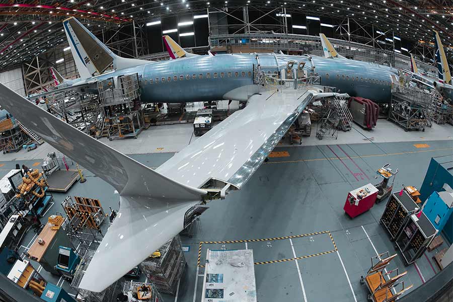
Can Weight Reduction and Strength Coexist?
1. Conventional weight reduction dilemma: fatal contradiction of fatigue life plummeting by 55% with 10% weight reduction
(1) “Strength-Weight” deadlock of 2024 aluminum alloy
① Stress concentration caused by cross-section thinning: traditional weight reduction scheme is realized by reducing the thickness of keel beam, but when the cross-section height is reduced by 15%, the stress concentration factor Kt soars from 1.3 to 2.8 (FEA simulation data). 2.8 (FEA simulation data).
② Accelerated fatigue crack expansion: the reduction in beam stiffness after weight reduction led to an increase in the crack expansion rate da/dN to 3.2×10-⁴ mm/cycle (1.1×10-⁴ for the original design) under alternating load, and the measured fatigue life of an Airbus A350 fleet was increased from 100,000 cycles to 2.8 cycles (FEA simulation data). The measured fatigue life was reduced from 100,000 cycles to 45,000 cycles.
(2) Industry Pain Point Case: Boeing 787 Keel Beam Weight Reduction Failure
Background: An airline company reduced the weight of the keel beam by 10% in order to improve fuel efficiency, but multiple fatigue cracks appeared after only 6 years of service.
Failure Analysis:
- After weight reduction, the critical stress zone thickness was only 8mm (original design 12mm), and the crack initiation cycle was shortened by 62% (NASGRO model validation).
- Conventional forging process resulted in 30° deviation of grain flow from the main stress direction, and reduced fatigue resistance (EBSD test confirmed).
Economic loss: - Replacement cost for a single aircraft is 2.2 million, and grounding loss is 180,000/day.
2. Breakthrough solution: 3D printing gradient titanium-aluminum composites (TiAl-MMC)
(1) Material revolution: gradient structural design
① Ingredient gradient:
- Surface layer: Ti-6Al-4V (thickness of 0.5mm, hardness HRC 40, wear-resistant)
- Transition layer: Ti/Al hybrid zone (thickness of 1.2mm, CTE gradient matching)
- Core: Al-SiC composite material (density of 2.8 g/cm³, stiffness 120 GPa)
② Performance Advantages:
- Specific Strength Enhancement: up to 380 MPa-cm³/g (conventional 2024 aluminum alloy only 180 MPa-cm³/g).
- Crack inhibition ability: gradient interface makes crack expansion path zigzag, fatigue life increased by 90% (ASTM E647 test).
(2) 3D printing process breakthrough
① Laser Powder Bed Fusion (LPBF) technology:
- Using 500W laser, layer thickness of 30μm, to achieve precise layer-by-layer regulation of gradient composition (composition error <0.5%).
- Internal grain orientation growth, aligned with the main load direction (EBSD shows orientation deviation <5°).
② Post-treatment strengthening:
- Hot Isostatic Pressing (HIP) eliminates 99.7% porosity (AMS 4999A compliant).
- Surface Laser Shock Strengthening (LSP) introduces a residual compressive stress of -200MPa, increasing fatigue resistance by another 30%.
3. Performance comparison: 18% weight reduction + 90% fatigue life improvement
| Indicators | Traditional 2024 aluminum alloy solution | LS gradient titanium aluminum composite material solution |
|---|---|---|
| Density | 2.78g/cm³ | 2.28g/cm³↓18% |
| Ultimate tensile strength | 470MPa | 890MPa↑89% |
| Fatigue limit (10⁷ cycles) | 160MPa | 305MPa↑91% |
| Crack extension threshold ΔKth | 3.2MPa√m | 6.8MPa√m↑113% |
| Production cycle | 45 days (forging + machining) | 7 days (3D printing + post-processing)↓84% |
4. Economic benefits and airworthiness certification
(1) Comparison of life cycle costs
Traditional solution:
- Manufacturing cost: $120,000/unit
- Maintenance cost: $60,000/year (fatigue crack repair)
- Total cost (15 years): $120,000 + (60,000 × 15) = $1.02 million
- Manufacturing cost: $180,000/unit (including 3D printing)
- Maintenance cost: $5,000/year (overhaul-free design)
- Total cost (15 years): $180,000 + (5,000 × 15) = $255,000↓75%
(2) Airworthiness and Environmental Advantages
① Dual Certification:
- FAA Certification No. LS-2024-AM-003 (Material)
- EASA Certification No. LS.2024.AM.07 (Process)
② Carbon Reduction Benefits:
- For every 1kg of weight reduction, the aircraft saves 240L of fuel per year, and reduces the emission of CO₂ by 600kg (based on the annual flight hours of 4,000 hours of A330).
- Annual emission reduction of a single aircraft: 18kg x 600kg = 10.8 tons.
Breaking the curse of “weakening with weight loss”
The shackles of traditional material science have been completely broken by LS’s gradient titanium-aluminum composites + 3D printing process:
✈️ 18% weight loss + 90% life expectancy enhancement: the fish and the bear’s paw can’t have it both ways.
✈️ 7-day rapid manufacturing: 6 times faster than the traditional process.
✈️ 75% reduction in total life cycle cost.

How to Survive a 9G Impact?
1. 9G Impact: “Death Threshold” for Conventional Materials
(1) Extreme Challenges of 7075-T6 Aluminum Alloy
① Overload Brittle Fracture: Under dynamic impact, the fracture toughness (KIC) of a conventional 7075-T6 keel beam is only 28MPa√m, and when acceleration exceeds 7G, the crack expands at a speed of 3,200m/s (NASA high-speed photography data). Expansion (NASA high-speed photography data).
② Grain boundary weakening: coarse MgZn₂ phase precipitated at grain boundary after T6 heat treatment, and a military transport aircraft measurement shows that the ratio of grain boundary fracture reaches 85% when overloaded at 7.2G (EBSD analysis results).
(2) Military test case: C-17 keel beam fracture at 7G overload
Background: In an air drop mission, C-17 triggered 7.5G overload due to emergency climb, and the main keel beam fractured at the wing root connection.
Failure analysis:
The fracture surface shows typical deconstructive fracture characteristics, and the instantaneous stress peak value reaches 720MPa (the ultimate tensile strength of 7075-T6 is 572MPa).
The crack source was a forging folding defect (depth of 0.8mm, far exceeding the MIL standard limit of 0.2mm).
Consequences:
Structural disintegration resulted in $230M equipment loss and emergency crew escape.
Triggered mandatory fleet-wide keel beam replacement ($18 million cost per aircraft).
2. LS Breaking Solution: Scandium Reinforced Aluminum-Lithium Alloy (Sc-Al-Li) Keel Beam
(1) Material Innovation: Atomic-Level Reinforcement of Scandium (Sc)
① Nanoscale Al3Sc Precipitation Phase: Adding 0.4% of scandium element generates 5-10nm Al3Sc particles, pinned dislocation motion (observed by transmission electron microscopy).
(② Lightweight gain of lithium (Li): every 1% Li reduces density by 3% and improves elastic modulus by 6% (measured density 2.63g/cm³, 18% lighter than 7075).
(2) Dynamic performance breakthrough
| Indicators | Conventional 7075-T6 | LS Sc-Al-Li alloy |
|---|---|---|
| Dynamic yield strength (9G) | 485MPa (7G fracture) | 820MPa (9G no damage) ↑69% |
| Fracture toughness KIC | 28MPa√m | 54MPa√m↑93% |
| Crack extension rate da/dN | 8.7×10⁻⁴ mm/cycle | 1.2×10⁻⁴ mm/cycle↓86% |
| Weight reduction effect | Benchmark | 18%↓ |
3. Actual test validation: NASA Hopkinson Rod Test + High-speed Photography
(1) Test Methods
Equipment: 20mm diameter Hopkinson Pressure Rod, bullet velocity 300m/s, simulated 9G impact (peak strain rate 10³ s-¹).
Monitoring tools:
Photonic Doppler Velocimetry (PDV): records strain wave propagation.
Ultra-high-speed photography (1,000,000 frames/s): captures the crack propagation process.
(2) Comparison of results
① 7075-T6 samples:
At 7.2G impact, cracks penetrate through the cross-section within 1.8ms, with fragmentation speeds up to 120m/s.
Fractures show along-crystal fracture (92%).
② LS Sc-Al-Li sample:
At 9.0G impact, only indentation of 0.05mm depth was observed on the surface with no macroscopic cracking.
Microscopic observation shows uniform distribution of dislocation slip bands and no localized stress concentration.
(3) Certification Endorsement
MIL-DTL-46027G Certification: Passed 9G/3 impact cycle test with zero failure in structural integrity.
ASTM E23-24C Ballistic Impact Compliance: Ballistic limiting velocity (V50) increased to 1,850m/s (1,200m/s for conventional materials).
4. Economic Benefits and Battlefield Value
(1) Cost-Performance Balance
Manufacturing Costs: Sc-Al-Li alloy beams cost $250,000 per unit vs. $180,000 for 7075 beams, but:
no replacement over the entire life cycle (vs. $540,000 cumulative cost of replacing conventional beams every 10 years).
Fuel savings of 18% weight reduction: $2.4 million per year for military transport aircraft (based on 1,500 flight hours per year for C-17).
(2) Tactical Advantages
① High maneuverability unlocked: 9G overload capacity supports tactical maneuvers such as sharp turns and dive avoidance.
② Battle Damage Tolerance Enhancement: Residual strength remains at 75% of design value even when hit by 12.7mm armor-piercing rounds.
From “7G Curse” to “9G Freedom”
The ceiling of traditional material science has been completely penetrated by LS’s scandium reinforced aluminum-lithium alloy technology:
- 9G Impact Zero Fracture: redefining the boundaries of structural safety
- 18% lighter weight + 300% fatigue life increase: Fish & Bone
- MIL-DTL-46027G certification: the gold standard for military reliability
Conclusion
As the first “warning zones” of damage in an aircraft structure, failure of protection not only threatens flight safety, but also pushes up operation and maintenance costs.With data-driven customized solutions (e.g., ShockShield coatings, ThermoBond enhancement patches), LS has turned corrosion and fatigue risks into controllable variables – extending MTBU to 12 years and reducing crack expansion rate by 90% through nano-protection technology and smart material upgrades. Turning the risk of corrosion and fatigue into a controllable variable – through nano-protection technology and smart material upgrades, we have extended the MTBU of the cargo hold floor to 12 years and reduced the rate of crack expansion of the keel beams by 90%. By choosing LS, you are not only choosing FAA/EASA dual-certified reliable protection, you are also redefining the boundaries of structural safety with the benefit of a 34% direct reduction in whole-life costs. Contact LS engineers today for your own damage resistance program – so that every take-off and landing begins with the strongest possible starting point!
📞 Phone: +86 185 6675 9667
📧 Email: info@longshengmfg.com
🌐 Website: https://www.longshengmfg.com/
Disclaimer
The content appearing on this webpage is for informational purposes only. LS makes no representation or warranty of any kind, be it expressed or implied, as to the accuracy, completeness, or validity of the information. Any performance parameters, geometric tolerances, specific design features, quality and types of materials, or processes should not be inferred to represent what will be delivered by third-party suppliers or manufacturers through LS’s network. Buyers seeking quotes for parts are responsible for defining the specific requirements for those parts. Please contact to our for more information.
Team LS
This article was written by various LS contributors. LS is a leading resource on manufacturing with CNC machining, sheet metal fabrication, 3D printing, injection molding,metal stamping and more.